Rotation, moment of inertia, torques, angular momentum, gyroscopes and precession: this page gives more detail to support the multimedia tutorial Rotation.
This demonstration, also shown in the multimedia tutorial on rotation, illustrates rotational kinetic energy. The brass object initially rolls on two inclined rails that support it by contacting its shaft. At the end of the incline, it reaches a horizontal track on which it rolls on its edge. This happens at about t = 4s on the clip.
The vertical time markers show how far it travels in each second. Going down the ramp, it accelerates smoothly. Notice that it suddenly accelerates when it reaches the horizontal track. This is not surprising: relative to the centre of the object, the edge is moving faster than the surface of the shaft (see rolling). So, when the edge contacts the horizontal track, it exerts a frictional force against it. The tract exerts an equal and opposite force, which accelerates it.
This sudden acceleration required energy: where was it stored?
When the rapidly moving edge contacted the horiztonal track, some of the rotational kinetic energy is converted into translational kinetic energy: on the level track, it is travelling faster but rotating less rapidly. (Some kinetic energy is also lost, however, because there would be some skidding during this process, so some energy lost. See the section on contact forces.)
Now let's get quantitative.
Rotational kinetic energy
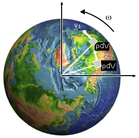
Let us picture a rigid body turning with angular velocity ω, like the Earth in this picture. Mentally, let's divide it up into a collection of small masses. With respect to the axis of rotation, a single mass m at radius r is travelling at speed of
v = rω
(You may wish to revise circular motion at this point.) Its kinetic energy is ½ mv2. So
let's imagine the dividing the object up into many masses mi at distances ri from the axis. Each has vi = riω, where ω has the same value for all the masses because the object is (by assumption) rigid. So the total rotational kinetic energy is
Krot = Σ Ki = Σ ½ miri2ω2
where the summation is over all of the i. ½ ω2 is a common factor in every term of the sum, so
Krot = ½(Σ miri2)ω2 = ½ Iω2 where
I = Σ miri2 is the moment of inertia.
This is the result for a collection of discrete masses, mi. For a continuous body, we should normally divide it up into small elements of volume, dV. (You may wish to revise calculus.) From the definition of density ρ, each has mass
dm = ρdV.
Instead of an ordinary summation, we do an integral (the equivalent of summation for very small divisions), and we have
Krot = ½(∫ dm.r2)ω2 = ½ Iω2 where
I = ∫ r2.dm is the moment of inertia for a continous body
and where the integration is over the whole volume occupied by the rigid body in question.
Students often ask at this stage: 'I know how to integrate over x, y etc, but how do I integrate over mass?' The answer is via the density, ρ. To know the mass distribution, you need to know ρ(r) or ρ(x,y,z). So we consider a small element of volume dV, and write dm = ρ.dV. If the object had rectangular symmetry, we might choose dV to be a cube with sides dx, dy and dz and write, for that example,
dm = ρ.dV.z = ρ.dx.dy.dz.
Then we just integrate over the limits of x, y and z that define the object being studied. For a sphere or a solid cylinder (about their axes), however, the volume elements would be hollow cylinders about the axis, and the integration would go from zero radius to that of the sphere.
In the examples below, the value for the hoop is obvious: all of the mass is at distance r, so I = mr2. The disc about its axis can then be considered as a set of hoops, each of thickness t and width dr, and having mass dm = ρdV = ρ.2πt.r.dr. The sphere may be considered as a set of discs with different radii. The rectangle and the disc about its diameter are both analysed as sets of rods. There are examples in most textbooks. I'll put some up here soon, but shall postpone it because it's hard to write maths in html!
Moment of inertia
Here are some useful common cases that result from the integrals referred to above.
Rolling problems
This is one of the puzzles introduced in the multimedia tutorial. Two similar jars, one full of water (low viscosity) and one full of honey (high viscosity). Which one rolls faster? Before your run the film, ask yourself these questions: Assuming their weights are the same, what can you say about their initial potential energies? When they reach the bottom, which will have more rotational kinetic energy? And therefore, which will have more translational kinetic energy?
You should be able to use similar arguments, and the values of moments of inertia given above, to predict the results of most of the 'races' shown below. But first we might ask whether size comes into it, either via radius, or via mass. The clip below shows two aluminium discs of different sizes but the same mass.
The next race is between a disc (a solid cylinder) and a hollow cylinder.
A solid sphere (a billiard ball) and a solid disc (of aluminium).
And, finally, spheres of different sizes and masses. (two steel balls)
Rotational kinematics
As mentioned in the multimedia tutorial, there are very strong analogies between linear and rotational kinematics. If s is the distance of the arc travelled along a circle of radius r, then angular displacement θ is just s/r. Angular velocity ω = dθ/dt = (ds/dt)/r = v/r. Angular acceleration α = dω/dt = (dv/dt)/r = a/r.
So, as shown in the diagram below, the analogies of the linear quantities s, v and a are θ, ω and α, which we obtain by dividing the linear quantities by r.
The graphs above show displacement, velocity and acceleration for linear motion with constant acceleration (at left) and for circular motion with constant angular acceleration. Just for practice, let's derive the new equations (and revise the kinematics section if this looks difficult!) If we consider motion with constant acceleration, and remember that α = dω/dt, we have
ω = ∫ α dt = αt + ω0
And from ω = dθ/dt, we can integrate again to get:
θ = ∫ ω dt = ½αt2 + ωt + θ0
From the two equations above, we can eliminate t to get
ω2 − ω02 = 2α(θ − θ0).
So we have equations completely analogous to those of linear kinematics:
ω = ω0 + αt and θ = θ0 + ω0t + ½αt2 and ω2 − ω02 = 2α(θ − θ0)
v = v0 + at and s = s0 + v0t + ½at2 and v2 − v02 = 2a(s − s0).
Torque: dependence on displacement, force and angle
As we saw in an earlier section, forces cause accelerations. To make something turn, we apply a torque. We shall define if first, and then explain why this defintion is logical. Later we shall see the complete analogy with Newton's laws for linear motion.
The torque τ is defined by
τ = r X F
where force F acts at a point displaced by r from the axis. The magnitude of the torque is given by
τ = r F sin θ
where θ is the angle between r and F. (You may need to look at the cross product section of the support page on vectors.)
We shall discuss the magnitude first, then the direction.
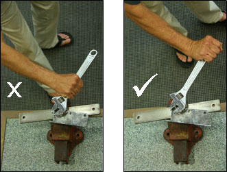
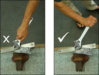
The photos at right show three ways of using a spanner. In the first pair, we compare a small value of r (small torque) with a large r and large τ. In the second, we compare θ = zero and θ = 90°. In the former case, the torque is zero. From experience, you know that you need large r, θ = 90° and large F to obtain the maximum torque.
Torque is also known as moment of force or sometimes simply as moment. r sin θ is known as the moment arm.
This upper set of diagrams at right shows the dependence of torque on the angle θ. Maximum torque occurs when the component of F at right angles to r is maximum, i.e. when θ = 90°. The central figure shows the tangential component of F, which is F sin θ.
The equation
τ = r F sin θ
can be interpreted in two different ways, as shown in these sketches:
τ = r (F sin θ) or τ = F (r sin θ).
We can think of it as r times the tangential component of F (left sketch and equation) or as F times the shortest distance (r sin θ) between the axis and the line along which F acts (right sketch and equation).
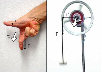
Torque is a vector
The definition τ = r X F gives the direction of τ . It is at right angles to both r and F is in the right-handed sense: if you put your right thumb in the direction of r and your forefinger in the direction of F, your right middle finger points in the direction of τ. The second photograph shows the torque τ produced by the tension in the string about the axis of the pulley.
In an earlier tutorial, we saw that Newton's first and second laws for linear motion are combined in the equation
F = ma.
Force tends to produce linear acceleration, and mass resists linear acceleration.
For rotation, torque tends to produce angular acceleration, and moment of inertia resists angular acceleration. Considering just rotation about a fixed axis, we write Newton's law for angular motion as
τ = Iα
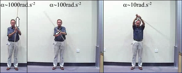
In these film clips, we see different torques τ giving rise to different angular accelerations α for objects with the same moment of inertia I. Although the same mass is attached to the string, the forces are only approximately equal: the force in the example at right is a little less than that at left. (Can you see why? Think of the equation of motion for the descending mass.)
Despite the somewhat smaller force in the second case, the larger displacement of the point of application from the axis means that the torque is greater in this case, and so it produces a greater angular acceleration.
In these film clips, we see the effect of changing the moment of inertia. Again, although the same mass is attached to the string, the forces are only approximately equal, but the approximation is better in this example. In these three case, the radius about which the force acts is the same, so the torques are approximately equal.
In the first film, an aluminium tube rotates. In the second, masses are attached to it, increasing its moment of inertia. Larger mass, larger I, smaller α. Comparing the second and third films, we see that it is not just the mass, but also the distribution of mass that determine the moment of inertia: when the masses are at large radii, I is larger and α is smaller.
This experiment shows the importance of the axis in determining the moment of inertia. I strongly recommend it to give you a feeling for τ = Iα. We use the equations for I given above. Let the rod have mass m, radius r and length L. About the long axis of the rod, its moment of inertia is that of a disc, which is only Ilong = mr2/2. (In fact, the perturbations to I due to its bending are larger than this.) About the central transverse axis, Icentre = mL2/12. About the transverse axis at the end, Iend = mL2/3. Because L ~ 50*r, this makes a very large difference to the (oscillating) angular accelerations I can provide in the directions shown by the arrows. (The film version is on the tutorial.)
Why does the rod fall faster than the ball? Or is that a trick question?
This little demonstration is a puzzle I'll leave to the reader. However, to get you started, I've drawn a diagram.
Angular momentum: Newton's laws for rotation
The angular moment, L, of a particle with momentum, p, displaced by r from the axis of rotation is L = r X p. Let's take the time derivative
dL/dt = d/dt (r X p) = dr/dt X p + r X dp/dt
If the axis of rotation is fixed, then dr/dt is v, which is parallel to p, so the first term on the right is zero. Newton's second law for linear motion sets the total force, F, equal to dp/dt, so the term on the right is r X F. Applying this to rotation, and using the definition of angular momentum, L, shows us that the torque r X F, which is the definition of torque τ. So this gives us another of the useful analogies between linear and rotational motion:
F = dp/dt and τ = dL/dt
A consequence is that, if external torques are zero, angular momentum is conserved.
Observe the demonstration at top right. The chair spins freely, suggesting that external torques are small. So the questions are: when I draw in my arms,
what happens to my angular momentum?
what happens to my angular velocity?
what happens to my kinetic energy?
Let my moment of inertia be IJoe = mk2, where I estimate that k, my radius of gyration, is about 0.15 m. My mass is 70 kg so
IJoe = mk2 ~ (70 kg)(0.15 m)2 ≅ 1.6 kg.m2
The masses I am holding are 2.2 kg each. They are about 0.8 m from the axis of rotation when my arms are extended and about 0.15 m when my arms are drawn in. In these conditions, their moments of inertia are
For this crude calculation, neglect the moments of inertia of my arms and of the chair and we have
(IJoe + 2Im)ωinitial ~ (IJoe + 2I'm)ωfinal
So the ratio ωfinal/ωinitial is about (IJoe + 2Im)/(IJoe + 2I'm) ~ 2. You can check this by timing the periods with the arms in the two positions (and note that I only give the answer to one significant figure.
But what about kinetic energy? K = ½Iω2. Using L = Iω, we can write this as K = ½Lω. So, in this case, my kinetic energy increases by a factor of about 2 when I draw in my arms. So the question for you is: Why is my mechanical energy not conserved?
Angular momentum in collisions
In this example, the ball is thrown to the right of my axis, and also the (vertical) axis about which the chair can rotate. So, with respect to to that axis the angular momentum of the ball, when thrown to me, is downwards (or, if you prefer, clockwise viewed from above).
Consider the angular momentum of me, the chair and the ball, all about this axis. Because the chair turns easily on this axis, the external torque (through the chairs bearings) give a negligible angular impulse, so angular momentum about this axis is conserved: after the (completely inelastic) collision, we turn together.
There is a second collision, in which I throw the ball, giving it an angular momentum (always about the same axis) that is upwards (or, if you prefer, counterclockwise). The result is an increase in my angular momentum in the downwards direction.
Safety warning: the thrown ball also has an angular momentum about a horizontal axis at the level of the floor. If its value is high enough, it could cause the chair to tip over backwards. So don't throw it hard.
Gyroscopes
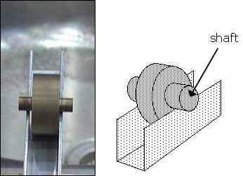
A gyroscope consists of an object with substantial angular momentum – which usually means it has a reasonably large moment of inertia and that it is spinning with a large angular velocity. It often has a gimbal mounting, as is the case here: its axle is mounted, with low frictional torque, in a frame with an axle at right angles to it, and that mounting is mounted in another frame whose axle is again at right angles, again with low frictional torque. This allows the last frame to be rotated in any direction with respect to that of the axis of the gyroscope without exerting much torque on the gyroscope.
Consequently, the angular momentum of the gyroscope is (approximately) conserved, in an inertial frame. So, for example, an ideal gyroscope whose axis of rotation points at a distant star would continue pointing towards that star, even if the vehicle/ aircraft etc in which it was mounted turned, pitched or yawed many times.
Precession
Let's apply
τ = dL/dt
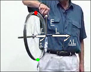
to the motion of a rapidly rotating object, such as the wheel in the movie at right. At the moment shown by the upper still picture below the movie frame, the wheel is spinning clockwise when viewed from the left, so its angular momentum L
is to the right, as the arrow shows. If we consider torques about the centre of the wheel, the weight exerts no torque about this point, but the string exerts an upwards force
F displaced by r from that point, so the torque τ = r X F due to the string is in the direction shown. Now ΔL, the change
in angular momentum, must be parallel to τ, so the L, which lies along the axle as shown, must move outwards towards the viewer.
Further, the torque is always (approximately) perpendicular to L, so the motion is circular – it is called precession.
How fast does it precess? If we make the approximation that the shaft is horizontal, then the angle dφ through which it precesses in time dt is just
dφ = dL/L so
dφ/dt = (dL/dt)/L = τ/L
The precession rate is proportional to the torque, so increased lever arm for the weight makes it precess faster. But an increased rate of spin ω would increase L and thus make it precess more slowly.
A warning: torque and angular momentum behave differently from some other vectors with regard to symmetry. For example, imagine a mirror placed to the right of this photo, and with its normal pointing to the left. The mirror image of the wheel would have an angular momentum pointing to the right. For this reason, torque and angular momentum are sometimes called pseudo-vectors. That they are less real than say force and linear momentum can be argued by pointing out that, if we changed the direction of the cross product by π, our unchanged equations would still work, but all torques and angular momenta would now by in the opposite direction. So, for that very reason, you might therefore wish to read:
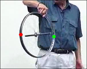
Can we explain precession without vectors? Qualitatively, the answer is yes. At right above are two stills taken from the movie: look at the top one. The cord on the right hand side (looking at the photo) is pulling the shaft up, the weight of the shaft is pulling it down. If it were not spinning, we know that the whole apparatus would tip anticlockwise: the top of the wheel would move left and the bottom would move right. So how does the spinning make it precess instead of falling?
Let's consider a small part of the rim of the wheel at the top – call it the top piece, and let's colour it red. At the instant of the top photograph, the top piece is travelling (for a very short time) horizontally, outwards from the photo, at high speed. But the combined effect of weight and the tension in the cord, as we mentioned above, makes it tend to move to the left. In fact, it does go to the left a little bit, but it also comes very rapidly out towards us. Just for this explanation, let's say that, after it has moved a quarter turn around the shaft, it will have come out towards us and be now the closest part of the wheel to us (and going downwards), but it will be displaced a tiny bit left with respect to left side of the rim in the (top) photo.
Similarly, let's consider a small part of the rim of the wheel at the bottom, and let's colour it green. At the instant of the photo, the bottom piece is travelling horizontally, into the photo. This time, the combined effect of weight and the tension in the cord makes it tend to move to the right. So again, let's say that, after it has moved a quarter turn around the shaft, it will have gone inwards, away from us and be now the furthest part of the wheel from us (and going upwards), but it will be displaced a tiny bit right with respect to the rim in the upper still photo.
So, after a quarter of a turn, the closest bit of the wheel will have moved slightly to the left, and the far side of the wheel will have moved a bit to the right. So we look at the bottom still (and then run the movie above) and we see that that is exactly what happens. The two coloured bits of the wheel are moving as expected from their weight and the tension in the cord (i.e. the external torque), but they don't have time to move very far because of their rapid rotation. The combination of these motions, and those of all the other parts, gives us the precession we see. Note, too, that the faster the wheel turns, the less time there is for the pieces to move sideways, so the slower the precession, as given by the equation above.
This explanation is rather longer than the vector explanation given above, and it's only qualitative. So a physicist or engineer needs the vector analysis, and can use it quickly and accurately. Perhaps s/he will sometimes use a qualitative explanation like this one as well, but it's a very slow route to an only qualitative result.


 This upper set of diagrams at right shows the dependence of torque on the angle θ. Maximum torque occurs when the component of F at right angles to r is maximum, i.e. when θ = 90°. The central figure shows the tangential component of F, which is F sin θ.