| |
|
|
EXPERIMENTS WITH MIXING COLOUR
This series of investigations involves experiments using cheap and simple equipment to investigate some of the many ways whereby colours can be mixed. The methods to be investigated include the following: Additive mixing. The light from different sources is present simultaneously at the same point in space. Partitive mixing. In this situation the light from different sources is not present simultaneously at the same point in space. There are two possibilities for partitive mixing
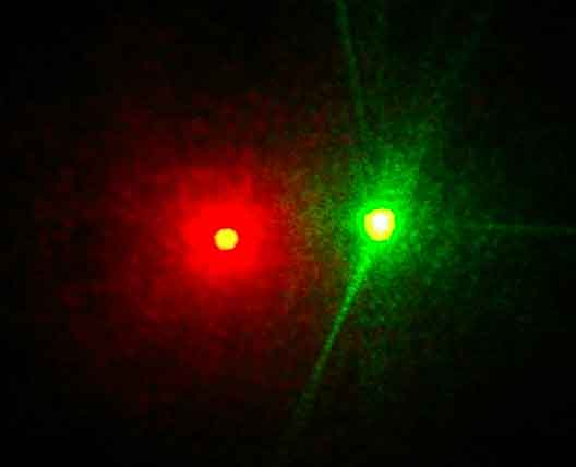
Subtractive mixing. The light from a sources passes through materials that successively subtract colours from the source. Light itself is not coloured because colour is a purely subjective human phenomenon – a distinction that was by first realised by Newton. However I will save space by referring to 'red light' rather than 'light comprising wavelengths that would induce the sensation of red when viewed by a typical observer', etc, etc. In these experiments we will not consider the detailed spectral characterisics of the colours we use; this will be considered in a further set of experiments. 2.1 Additive mixing of laser light The output of laser diodes is reasonably monochromatic with the energy centred on a single wavelength. The availability of relatively cheap red and green laser pointers allows an easy experiment. WARNING: Never look directly at a laser pointer, or shine it at someone else. Also be careful about 'specular' reflections; i.e. those from mirror–like surfaces. First arrange a red and a green laser pointer so their outputs fall side by side on a white sheet of paper – distinct red and green dots will be seen . If one laser is noticeably brighter than the other, its output can be reduced by passing it through some plastic or a filter (crossed polarisers can also be useful). 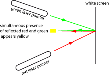
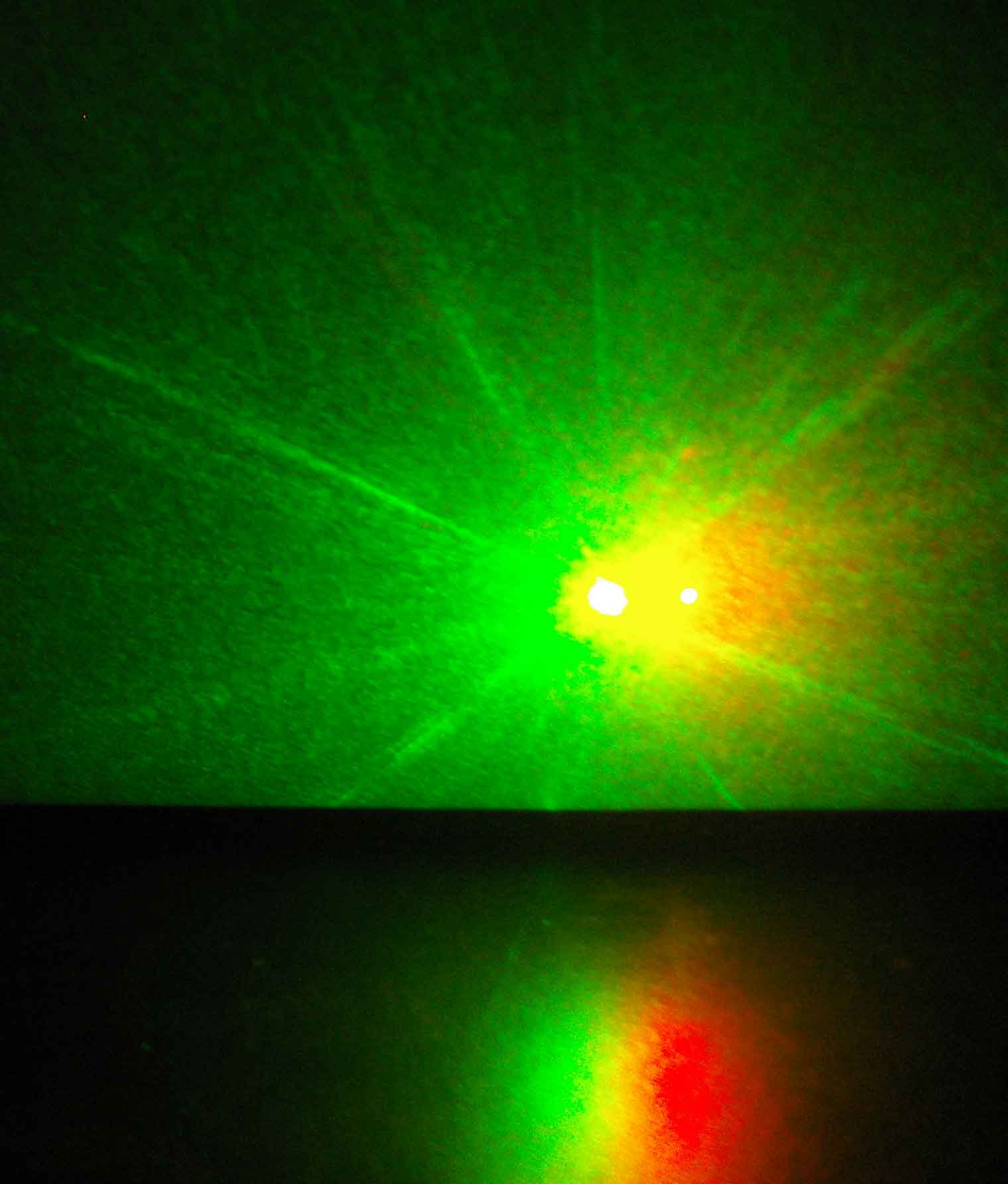
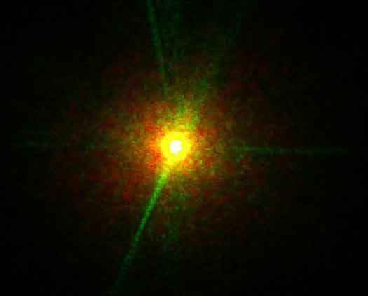
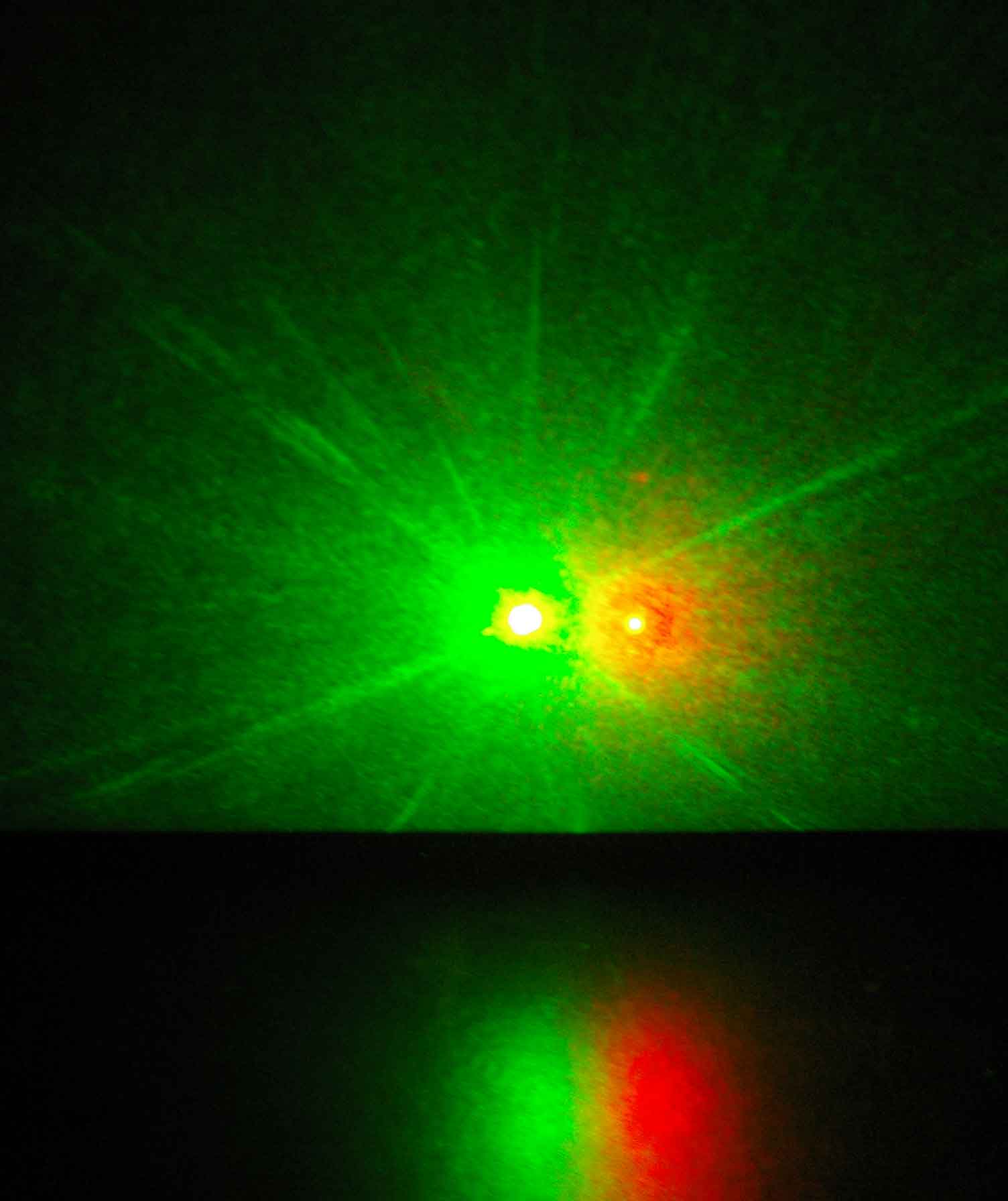
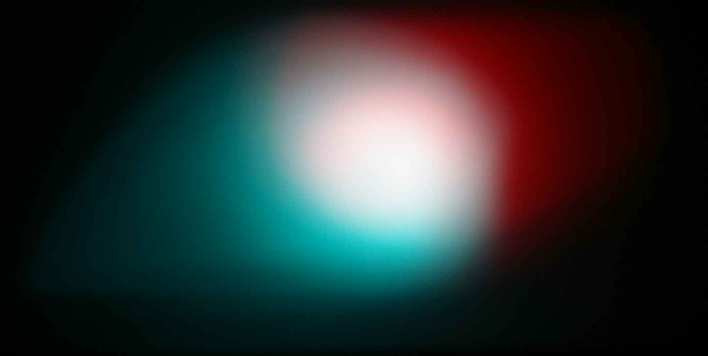
Now move the lasers so that their beams overlap; the combined dot will become yellow/orange. The scattered light from the lasers is intense and consequently their centres are overexposed in the photographs below and appear white. However the change in colour around the central beam can be clearly seen.
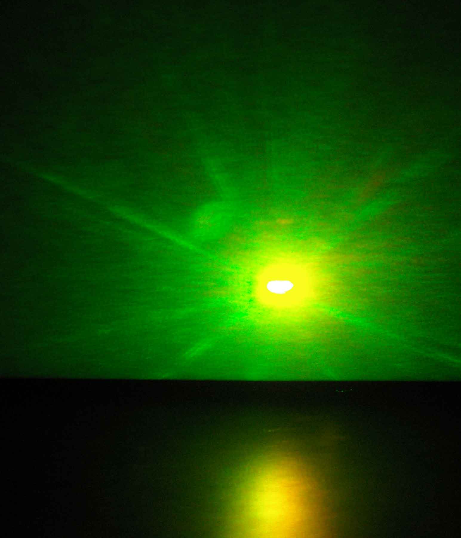
The change in colour as the beams progressively overlap can be seen more clearly in the reflections from the screen onto a second sheet of white paper; they are visible at the bottom of the photographs shown below.
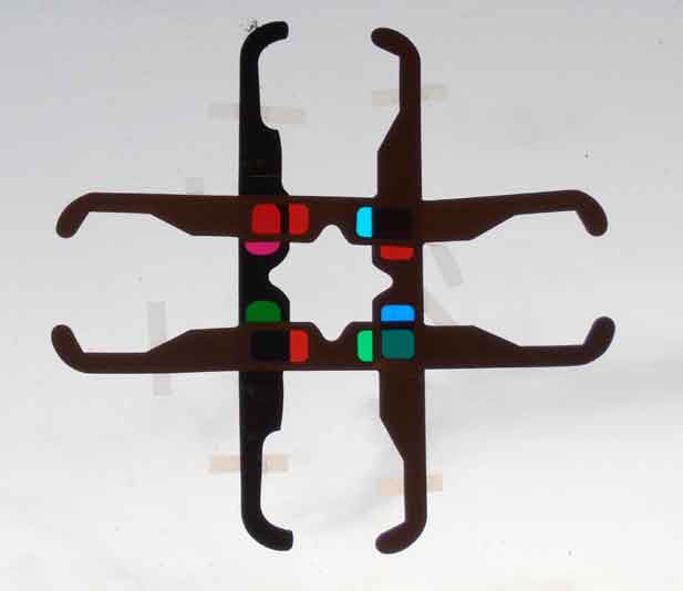
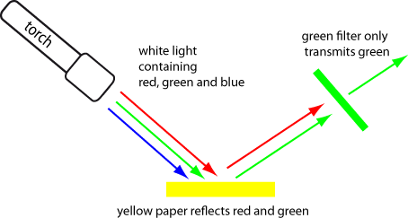
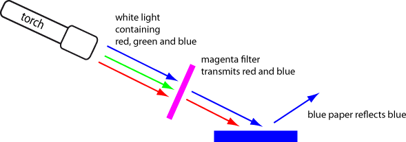
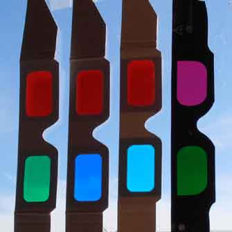
2.2 Additive mixing using light from torches with filters In this experiment we produce sources of coloured light by passing the white light from torches (flashlights) through filters that only pass a reduced range of wavelengths. The filters can be coloured glass, cellophane, plastic, etc. The filters I have used for these experiments are from the glasses used for 3D effects in computer games and some films (movies). These 'anaglyph' glasses have different coloured filters for the right and left eyes. There are several versions commonly available: red/green; red/blue; red/cyan; magenta/green. They are quite cheap; I bought the four different glasses shown in the photograph below via the internet at a cost of around A$1 each. If possible you might like to buy 2 pairs of each – you can then not only play 3D games with a friend, but also perform a wider range of experiments.
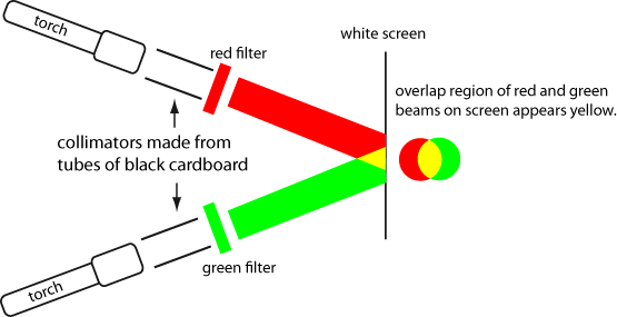
A schematic diagram of the experimental configuration using red and green filters is shown below. If the beams are carefully adjusted, the region of overlap should be yellow.
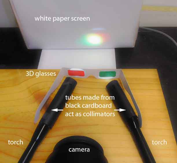
The torches I used were commonly available pocket versions constructed in aluminium that use 2 AA batteries and use a LED instead of an incandescent bulb. They have the advantage that it is possible to focus the beam by rotating the end of the torch. Some models also allow the light output to be reduced by 50% and/or 25% – this can be handy to allow for filters that transmit different amounts of light. However almost any torch that produces a reasonably uniform beam of light should be suitable. I found that a simple collimator – just some black cardboard rolled into a tube and fitted to the end of the torch – helped reduce stray light. In order to show clearly the experimental arrangement, the light on the screen from the torches is slightly overexposed in the photograph below – hence the overlap region appears white rather than yellow – see later the photos for correct exposure. Here is an example using red and green filters. If the beams are carefully adjusted, the region of overlap should be yellow.
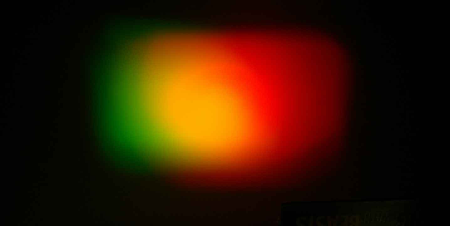
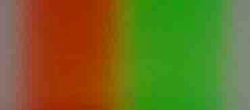
This is what I photographed on the screen with appropriate exposure– the yellow region can be clearly seen where the beams overlap. Towards the right of the overlap region the green beam is weaker and a shift in colour from yellow towards orange is apparent.
Although these filters work by passing a restricted range of wavelengths, the output within this range will usually still be reduced. Thus if the white light from one torch is passed through two successive green filters, the intensity of the green will be further reduced. In this case (shown below), the addition of green with reduced intensity to red produces an overall colour shift towards orange.
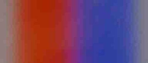
Using the red/blue anaglyph glasses gave the following.
With auitable levcels of intensity, the red/cyan glasses can produce white light – the cyan filter passes both green and blue which can add to the red passing therough the red filter
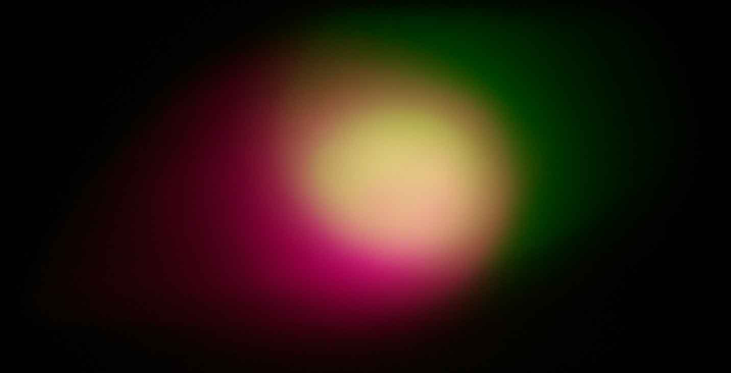
Here's what I photgraphed for the magenta/green anaglyph glasses.
If you have several sets of glasses and/or torches with adjustable levels of light output, there is a wide range of possible combinations to investigate. If you have a third torch, you can try combining red, green and blue to determine whether they can mix additively to produce white light. 2.3 Additive mixing using the light from a computer screen Your computer screen is capable of producing individual pixels that are a primary red, green or blue. The light from each pixel will then diverge as it travels away from the screen. If a semi-opaque screen is placed at a suitable distance, light from adjacent points on the computer screen will start to overlap. There are several possibilities for the semi–opaque screen. In the photographs below I have used tracing paper, but tissue paper or some other types of white paper or plastic used for packing can often be suitable. You can even use normal white paper, although a considerable grain is often apparent. 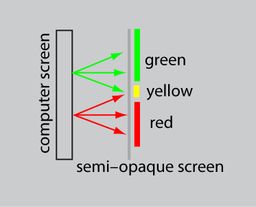
Look at the image below through your semi–opaque paper. If necessary, increase the brightness of your screen and reduce the level of ambient room lighting. 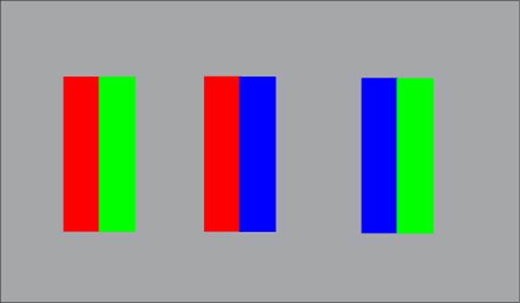
The photograph below shows what happens when I press a sheet of tracing paper against the above image on the screen. There is some blurring due to the paper, but no significant changes in colour 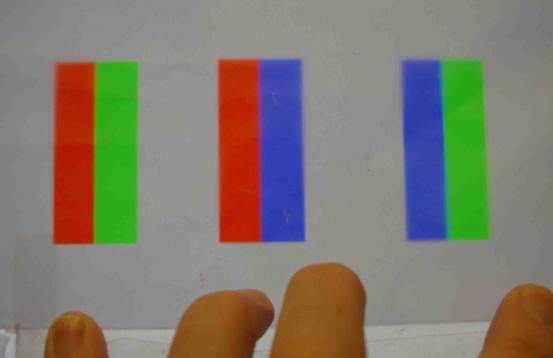
The photograph below shows what happens when the tracing paper is spaced slightly above the computer screen. I used a pencil, visible at the bottom of the photograph, to generate the desired spacing. A clear change in colour is now apparent at the boundaries between the colours 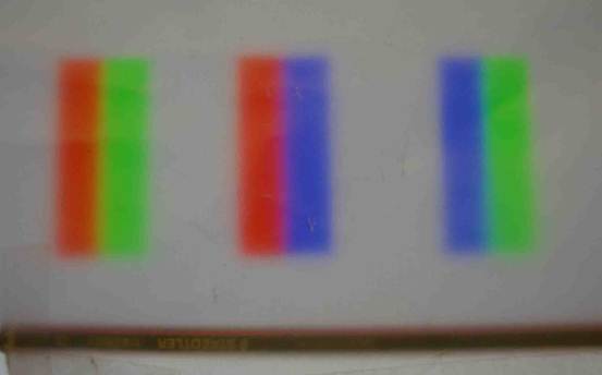
To show these colour changes in more detail, here are magnified images of the boundaries. There is a yellow/orange region between the red and green.
There is a cyan region between the blue and green. 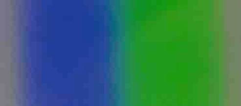
There is a magenta region between the red and blue.
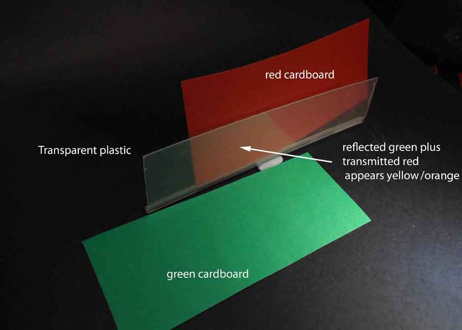
You can examine additive mixing between some other colours by drawing suitable images on the screen and using this technique. 2.4.1 Additive mixing using partial reflection and transmission from coloured paper In this experiment we take advantage of the fact that a clear material will not only transmit light, but can also reflect light. This allows us combine the transmitted light from one source with the reflected light from another source. For the transparent plastic screen, I used a piece cut from a takeaway food container for the photograph shown below. The clear cover of a CD box is also suitable.
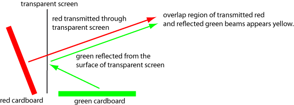
Here’s a photograph of what I saw.
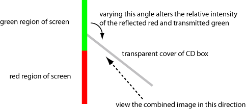
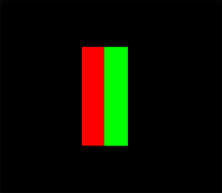
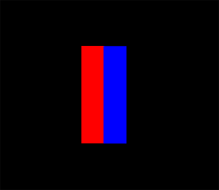
The effects of adding several different pairs of colours can be investigated in this fashion. Possible sources of coloured paper include the discs that can be printed for section 3.2. 2.4.2 Additive mixing using partial reflection and transmission from the computer screen In this version we use two coloured regions on the computer screen rather than two separate pieces of cardboard. For the transparent plastic reflective screen, I used the clear cover of a CD box. Hold the CD cover vertically and place on the green region as as shown below.
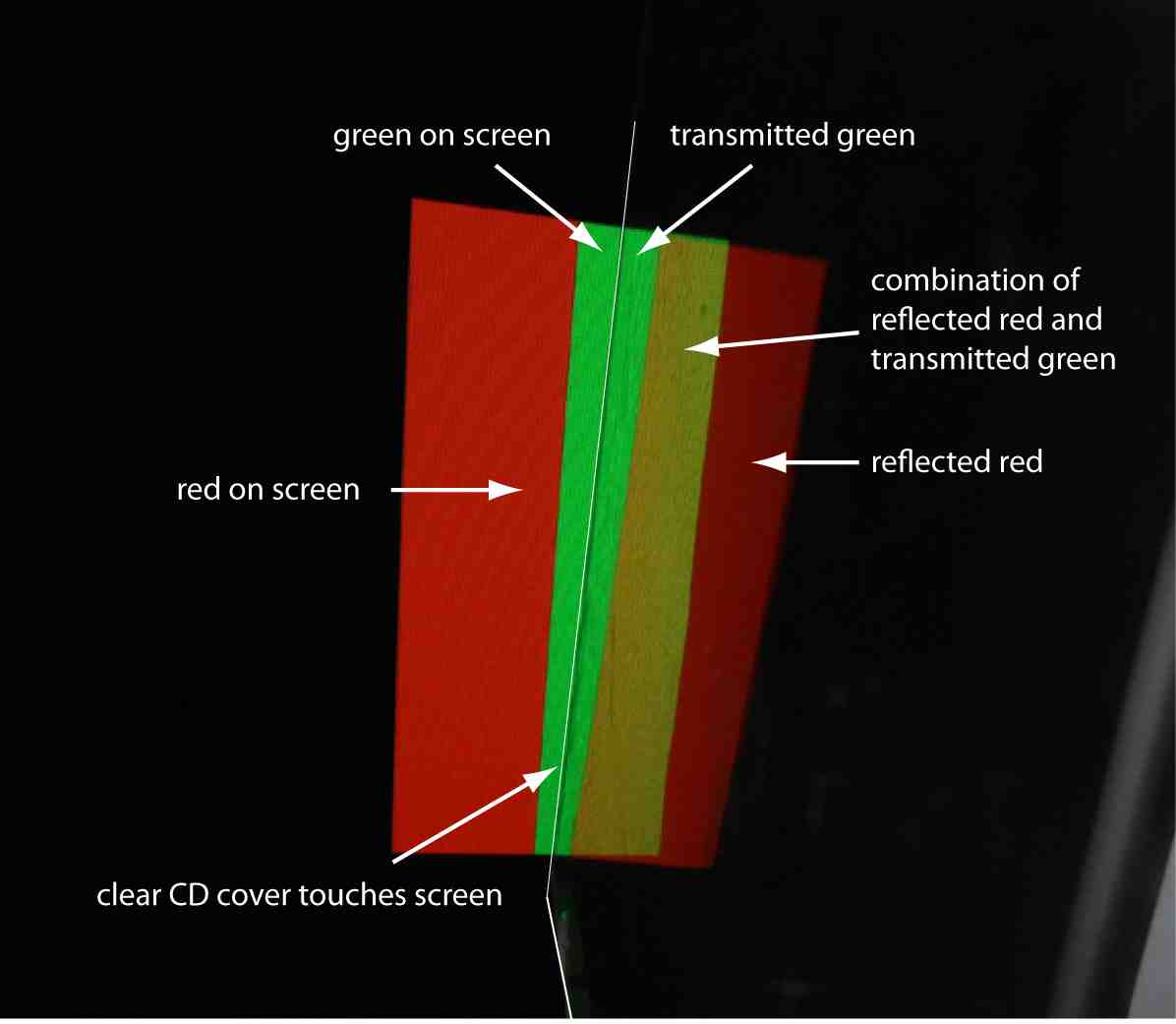
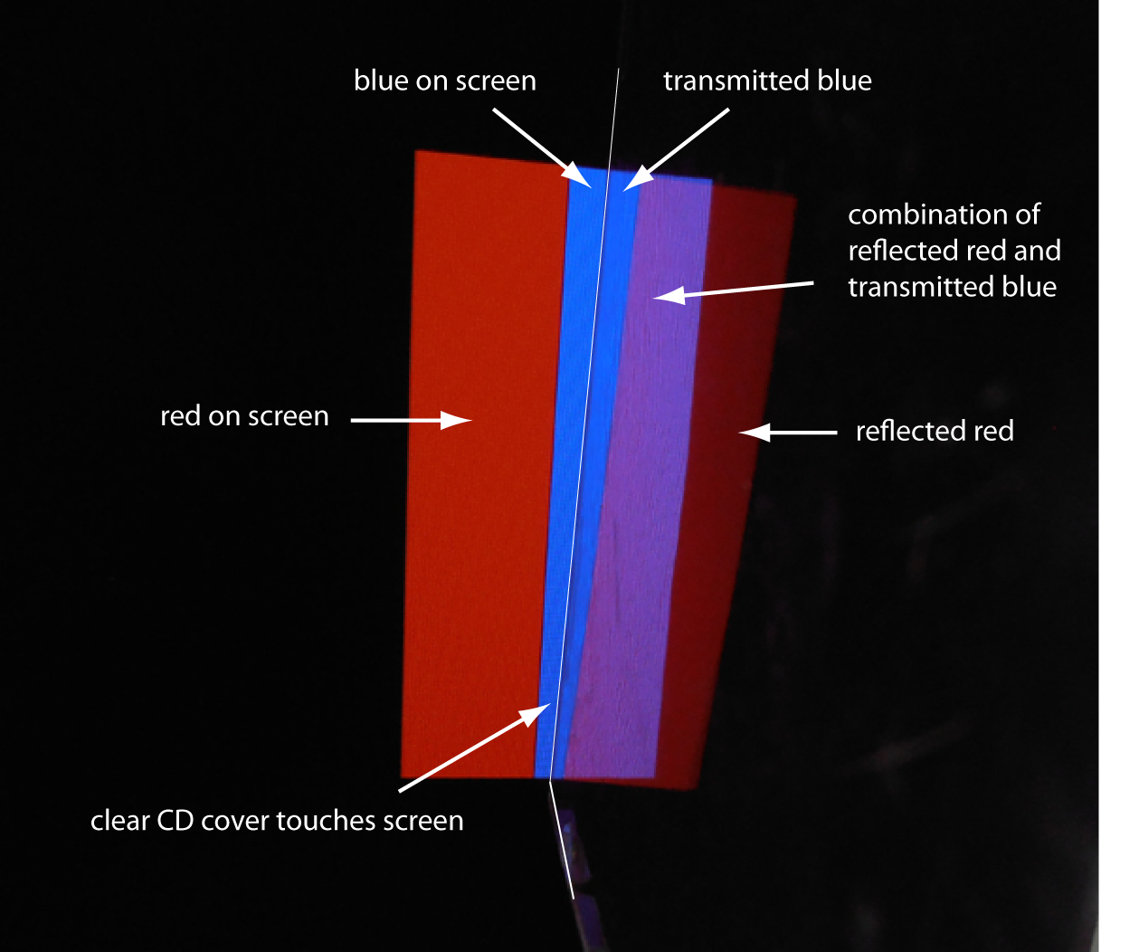
This photograph shows what my camera saw. The relative intensity of the two colours can be altered by carefully changing the angle between the CD cover and the screen. Now try adding red and blue. The photograph below shows what my camera saw.
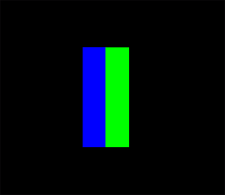
Finally try adding blue and green.
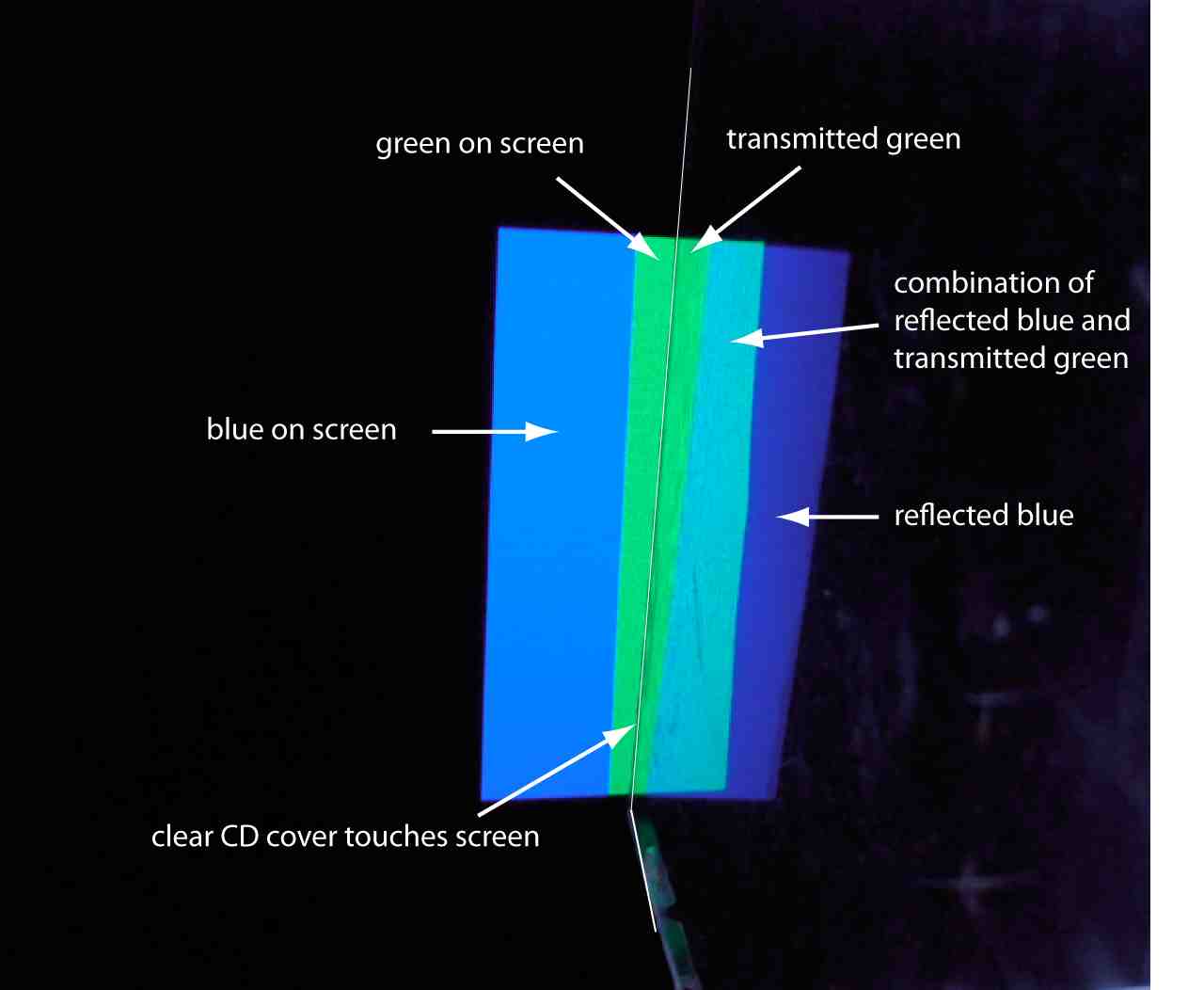
The photograph below shows what my camera saw.
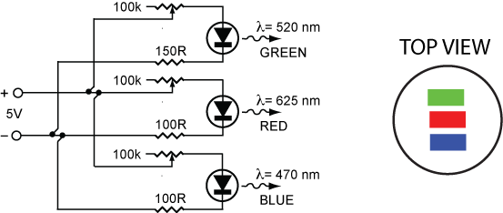
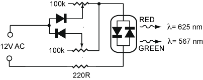
The effect of adding different pairs of colours can be investigated by drawing additional suitable diagrams on your computer screen. 2.5 Additive mixing using Light Emitting Diodes (LED) LED (Light Emitting Diodes) are a cheap source of reasonably monochromatic light. Several manufacturers sell units that contain individual red, green and blue LED within a single unit. The one I used for this experiment cost around A$5. If possible, use one with a “diffused” lens rather than a clear one. Otherwise use some sandpaper or abrasive on the surface of the unit to help diffuse the light from a clear unit. Wire up the circuit below. The intensity of a LED depends upon the current; the 100k potentiometers can now be used to control the relative levels of red, green and blue light. The fixed resistors (100R and 150R) in the circuit below are to limit the maximum current through the device. Manufacturers will usually specify values for some typical voltages; otherwise start with a high value (1k is usually a good choice) and reduce it until the LED is sufficiently bright.
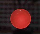
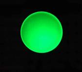
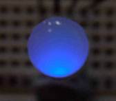
The photographs below show the unit when just the internal red, green or blue LED are used. ; The following photographs show what happened when two internal LED are used. For the red/green combination the transition from yellow at the centre to orange at the lower edge can be seen as the relative contribution of green decreases. Similar transitions in shading are apparent in the other combinations.
The photograph below shows what happens when all three internal LED are used. A photograph taken this close to the LED still shows some colour because of the spatial separation of the LED, but the intensity of the colour is much reduced 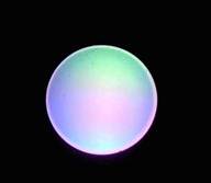
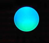
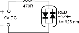
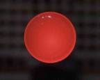
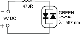
Adjusting the relative intensities of the red, green and blue LED with the potentiometers can produce a wide range of colours by additive mixing. 3. PARTITIVE MIXING OF LIGHT IN TIME In this type of mixing the light from different sources is not present simultaneously at the same point in space, rather the light from different sources falls sequentially on the same place. Providing this occurs more rapidly than the response time of the photoreceptors in the eye, the effect will be the average of the various sources. 3.1 Partitive mixing using alternating sources of light. In this experiment uses a red/green LED unit that has an individual red and green LED connected ‘back to back'. This means that it is impossible for both LED to be working at the same time. When connected to a DC source with one polarity the LED will be red.
When connected to a DC source of the opposite polarity the LED will be green.
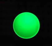
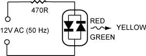
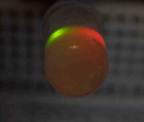
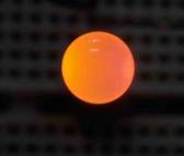
If connected to a supply of alternating polarity (an AC voltage) the unit will alternately display red and green. If this occurs more rapidly than the photoreceptors in your eye can respond, you will see the average of the two light sources. The left hand photograph below shows the LED driven by a small AC voltage. It was photographed at a slight angle so the individual red and green LED can be seen within the unit. The right hand photograph shows what happens when a much larger AC voltage is applied. The alternating red and green, although never present simultaneously, are combining to produce yellow. (Although a 50 Hz voltage works for the eye, we had to use a higher AC frequency for these 2 photographs).
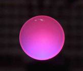
The intensity of the light from each LED depends upon the current flowing through it. The following circuit allows the brightness of each LED to be controlled by adjusting the 100k potentiometers. By reducing the current to the green LED relative to the red LED we can produce orange as seen in the photograph.
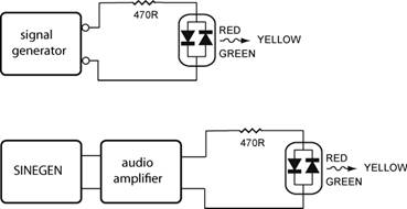
So far we have been using a 50 Hz AC supply, and accordingly the red LED will flash once during the positive part of each cycle and the green LED will flash once during the negative part of each cycle; consequently there will be 50 red and 50 green flashes each second. Because we see the combination as yellow, this rate must be faster than the response time of the photoreceptors. The circuits below allow us to control the rate at which the red and green flashes of light occur, and thus allow us to investigate the response time
Here is a movie showing what happens as the AC frequency is increased.
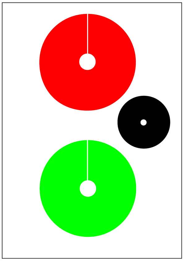
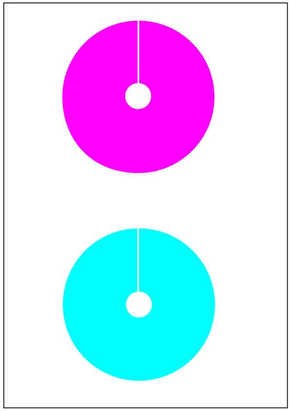
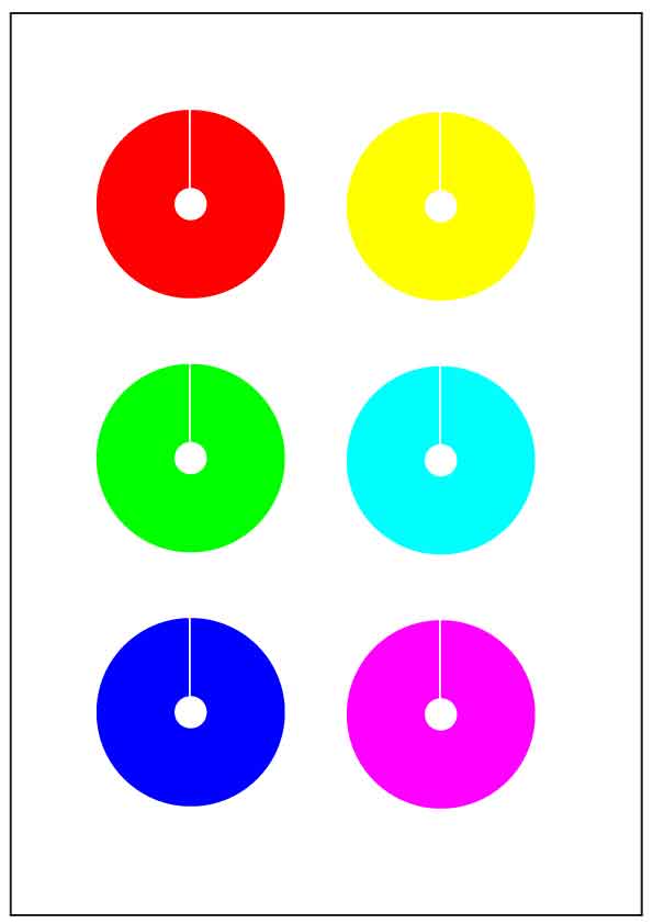
The distinct red and green flashes gradually combine until a yellowy-green colour results. A problem arises here bcause the optical characteristics of a digital camera are very different from the human eye – the response time of the camera is much faster. Here I have used a very low effective ASA rating and the lowest possible light levels so the simple point–and–shoot camera required as long an exposure time as possible. There can also be problems with frequency of the flashes beating with the frame rate. This exercise looks much better in real life rather than in this video. 3.2 Partitive mixing using spinning discs to reflect light. While he was a student, the great physicist James Clark Maxwell became intrigued by the color tops used by James David Forbes, his professo . By rapidly spinning the top, Forbes created the illusion of a single color from the several colours present on the disc. Maxwell took the coloured spinning tops invented by Forbes, and was able to demonstrate that white light would result from a mixture of red, green and blue light, and that virtually any colour could be produced by adding thes additive primaries. There are several ways you can repeat these experiments. (a) use a commercial top (b) make a simple top – here I have used an old CD mounted on a pencil. (c) Modify a personal, battery–operated fan. These are available for A$2 to A$3. Simply remove the fan blade, and use a fexible adhesivc to attach a plastic disc, I've found that the tops of takeaway sauce containers are ideal for the rotating disc. (d) use a power tool. A high speed electric drill or similar works well. WARNING: You should always use eye protection when high speed electric tools are used. Traditionally experimenters have used the reflections from coloured cardboard and/or paper. However the ready availability of excellent inkjet colour printers means that is easy to produce coloured discs in virtually any colour. Here are links to files that will allow you to print out sets of suitable coloured discs on A4 paper (if possible use high quality photo paper). The larger discs are a suitable size for mounting on a CD, the smaller ones will fit the top of a takeaway sauce container. They will produce a set of discs in the additive primaries (red, green and blue), and the subtractive primaries (cyan, magenta and yellow). A slit should be cut in each disc so that they can be rotatedwith respect to each other and their relative areas thaus varied.
Use these links to download the files for printing. Large red and green discs DISC-CD-RG-Print.pdf Large magenta and cyan discs DISC-CD-CM-Print.pdf Large blue and yellow discs DISC-CD-BY-Print.pdf Small discs in all colours DISC-TA-CMYK Print.pdf Here's an example of combining red and green. You won't produce a bright yellow because the reflected red light is only present half of the time, and so is the green light; consequently you are effectively mixing their combination with black.
Here's an example of combining red and blue.
Maxwell used spinning tops to perform a quantitative study. He used an approach whereby the colour produced by mixing two or three colours on the outside of the disc could be directly compared with the colour produced by different colours on the centre of the disc. This doesn’t require any colour memory and the comparisons are made under the same lighting conditions. This allowed the formulation of equations that describe colour mixing. Thus for the example shown below one could write that 0.5 red + 0.5 green = 0.44 yellow + 0.56 black
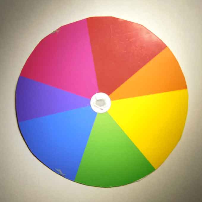
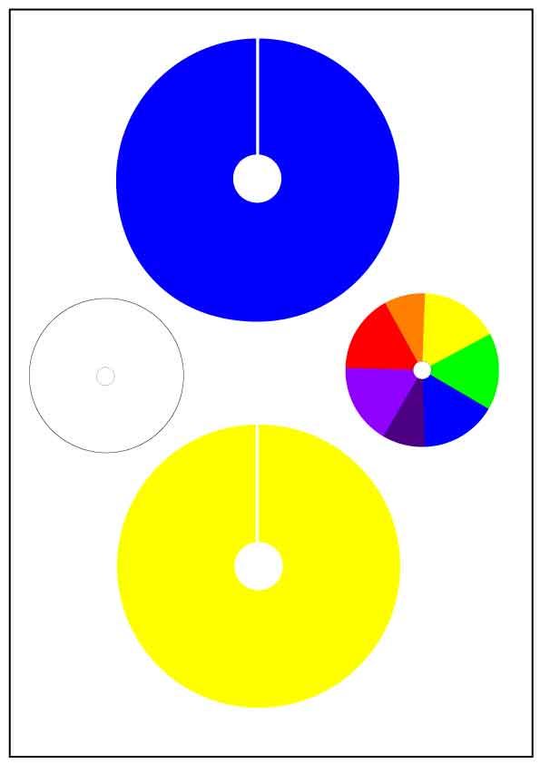
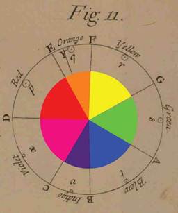
You can try this approach yourself using the large and small printed discs. Newton showed that white light could be decomposed into a continuum of colours. He developed a colour circle to explain the colours produced when different colours add. Unfortunately the number of colours (seven) was based on mystical considerations and the relative areas of the colours were assigned by analogy to the musical scale. Here these colours have superimposed the colours over the colour wheel from Newton’s “Opticks”
Consequently although it was an very original idea, it doesn’t quite work, e.g. the summing all the colours on the disc should produce white. You can try this yourself by using the small Newton disk on the printer files.
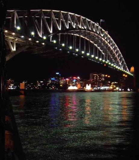
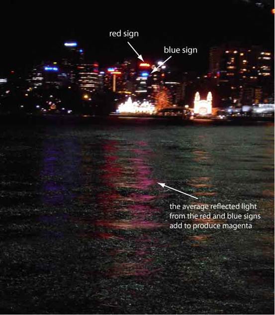
3.3 Partitive mixing via reflection. It is also possible to use reflection to partitively mix light. If the sea were beautifully flat with a mirror–like surface, two different coloured light sources would be seen as separate reflections. However the surface of the sea is usually covered by small ripples and waves that are caused by the wind, passing ferries and yachts, sharks, etc, etc. The photographs below show an example of how the reflections of a red and a blue advertising sign can add to produce a magenta reflection. It was taken late at night when I was walking after another great concert from the Sydney Symphony Orchestra at the Sydney Opera House. I used a hand–held camera, hence some blurring. The right hand photo was taken using telephoto.
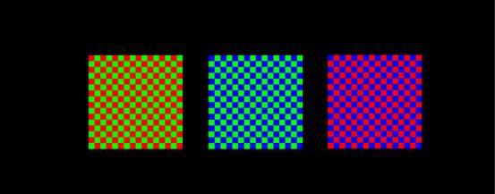
This example of partitive mixing probably occurs both in time and space. 4. PARTITIVE MIXING IN SPACE FOR LIGHT 4.1 Partitive mixing from adjacent regions on a computer screen. The figure below shows three squares containing chequerboard patterns made from red/green, green/blue and blue/red. When viewed from close to the screen, the colours are quite distinct. Now start to move away from the computer screen. As the individual red and green squares become smaller, the left hand square should start to appear yellow. Eventually, once the individual red and green squares can no longer be resolved, the square should appear to be a dark yellow colour. (If you have a small room or insufficient space, reduce the size of the images on the screen). The left hand square will not appear like the bright yellow you would normally expect on the screen. This is because yellow would normally be produced by the red and green sources within each individual pixel, whereas for the chequerboard patterns you only using only red in some pixels and only green in the others. Consequently you are combining only half the red and green when compared with the normal screen yellow; effectively you are mixing the yellow with black. This exercise can now be repeated with the green/blue and blue/red chequerboard patterns. You can make up your own patterns to investigate mixing other colours. This exercise can also tell you something about the spatial resolution of your visual system – more of this in a separate set of experiments.
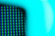
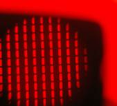
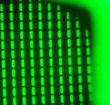
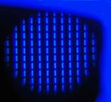
4.2 Partitive mixing using different screen pixels Your computer screen uses this partitive mixing in space to produce a huge number of colours. The individual light sources are very small (otherwise they would be noticeable), but they can been seen using a powerful magnifying glass, or a simple pocket microscope or magnifier. These microscopes are plastic with a magnification around 20X to 30X and usually cost around A10 to A$20. Probably one of the cheap USB microscopes that are now available would also suffice. The photographs below show the computer screen when photographed through one of these small pocket microscopes. In each case not only the individual pixels that generated the colour be seen through the eyepiece of the microscope, but also the screen colour produced by these pixels can be seen around the edge of the microscope. Red, green and blue are produced by activating only a single colour in each pixel.
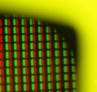
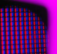
To produce any other screen colours, at least two colours need to be activated within each screen pixel. The following photographs show how yellow, magenta and cyan are produced.
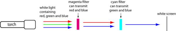
These individual colours within each pixel can also become visible if very small (and I mean very small) droplets of water are present on the computer screen. Each droplet can then act as the lens of a primitive microscope. I often notice this when use a very fine sparay of window cleaner to clean the computer screen. 5.1 Subtractive mixing using coloured filters One method is to shine a single source of white light through two filters. For example, the following diagram illustrates what might be expected for a magenta filter followed by a cyan filter.
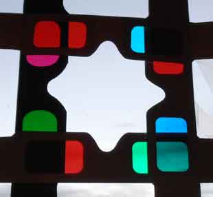
An even simpler method is just to hold the filters between your eye and a light source, perhaps a window. The following photos show some possibilities using the four different anaglyph glasses that I purchased. The left hand photo shows how they were attached to a window with adhesive tape; the right hand photo provides an enlarged viwe of the overlap regions between the filters.
The overlap at the top left shows that the subtractive mixing of red and magenta produces red. There are several other possibilities that can be investigated, especially if you have multiple sets of some glasses. 5.2 Subtractive mixing using reflection and filtering. Objects can appear coloured when viewed in white light because some wavelengths are absorbed (i.e. subtracted) and others are reflected. Thus red paper appears red because only wavelengths that produce the sensation of red are reflected while all the other wavelengths are absorbed. Subtractive mixing can thus be investigated by passing the coloured light produced by reflection through a coloured filter. The diagram belows shows how the reflection from yellow paper might appear when viewed through a green filter.
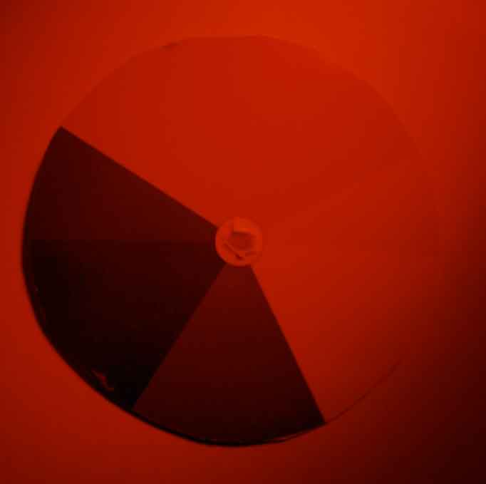
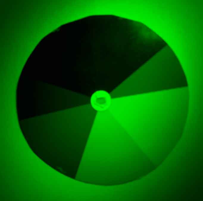
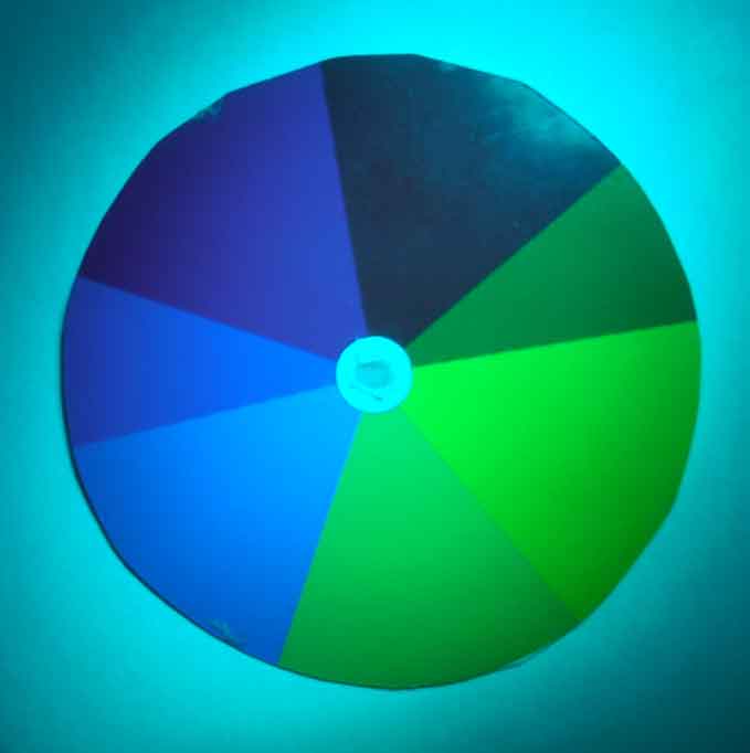
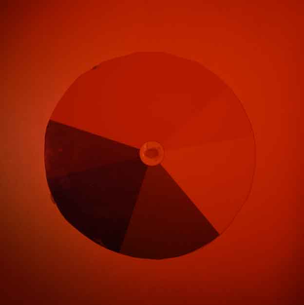
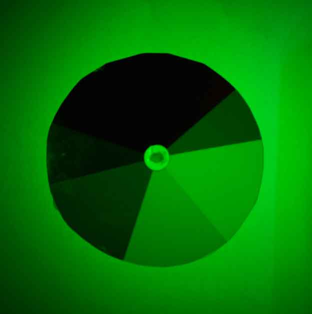
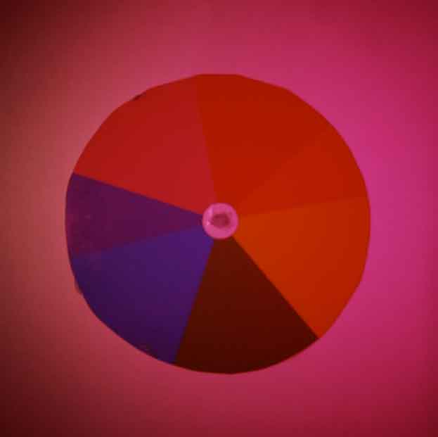
To investigate the reflections from several different colours I have mounted the Newton disc that was printed and used in section 3.2 on a sheet of white paper. The photographs below show what was photographed with no filter, a red filter and a green filter respectively.
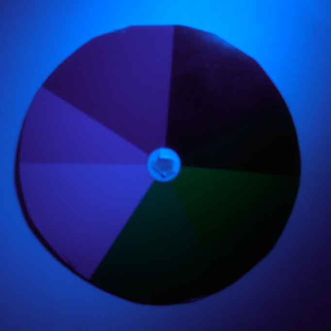
The photographs below show what was photographed with a blue filter, a cyan filter and a magenta filter respectively.
The subtractive mixing can obviously occur in the opposite order as shown in the diagram below. Here the coloured light is produced by passing white light through a coloured filter before it is reflected. The diagram below shows how the reflection from blue paper might appear when illuminated by light that has passed through a magenta filter.
The photographs below show the results for red, green and magenta filters respectively. As expected, they are very similar to those shown above;
5.3 Subtractive mixing using coloured pigments The coloured pigments used by artists fall into two main classes (i) transparent (often inks and watercolours) (ii) opaque (oils and acrylics) Here's an example showing how the additive primaries (red, green and blue) can be obtained by mixing the subtractive primaries (cyan, magenta and yellow).
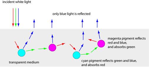
This diagram illustrates how the mixing of two transparent colours (cyan and magenta) on a white background can produce a new colour (blue).
Coloured pigments usually reflect a wide range of wavelengths, and so the results of their mixing can be quite complicated. This will be considered in further experiments.
|
|
||||||||


 .
.