Snell's laws quantifies refraction between two media. Here we use animations to illustrate and to derive Snell's law, then show an experiment to test the law and to measure the refractive index of glass. This page supports the multimedia tutorial Geometrical Optics.
Schematic showing the electric field, the 'wave crests' and rays in two media with different speeds of light.
In this animation, a vertical line separates medium 1 on the left and medium 2 on the right. The grey lines are rays showing refraction at the interface. The red lines represent 'crests' of the waves: points on these lines all have maximum value of the electric field. The histogram shows the electric field at the position indicated by the dot.
First, let's note that, at a point on the interface, such as the red dot, the number of wave crests that arrive from the left in a second equals the number that leave to the right. So the frequency is the same in the two media. In Travelling waves, we related wavelength λ to the frequency f and c, the wave speed: λ = c/f. So, with frequency the same in both media, the wavelength is shorter in medium 2, which has the slower wave speed, as shown in the animation. We shall now relate the wave speeds to the angles of incidence and refraction.
Snell's law: derivation
A still from the animation above: geometry relates the angles of incidence and refraction to the wavelengths in the media.
Two right-angle triangles at the interace, sharing the hypotenuse d, allow us to relate the wavelengths, λ1 and λ2, to the angles of incidence θ1 and refraction θ2. The refractive indexn1 for a medium is defined as the ratio of the speed of light c in vacuum to that in the medium, c1. Because the frequency is the same in the two media, the ratio of wavelengths equals that of speeds, so we have:
sin θ1/sin θ2 = λ1/λ2 = c1/c2 = (c/c2)/(c/c1) = n2/n1 , which gives
Snell's law: sin θ1/sin θ2 = n2/n1.
Snell's law: experimental determination of the refactive index
This experiment uses a narrow beam of light passing from air into glass and then to air. The experiment is practically easier using a hemicylindrical
prism of glass, with the beam entering from the curved side and travelling along a radius. Thus, at the air-glass interface, the angles of incidence
and refraction are both zero. By rotating the hemicylinder about the centre of its curved surface, however, we vary the angle of incidence, and thus that of refraction.
(The hemicylindrical is convenient, but not necessary for a home experiment: any prism of glass would do.)
An experiment to test Snell's law and to measure the refractive index for glass
For this experiment, we used six different angles of incidence. For the last few, we could distinguish clearly the angles of refraction for blue and red, so they are shown separately in the table and on the graph. To the precision of the measurements (indicated by the error bars), sin θair/sin θglass is a constant, which is nglass/nair. Because nair is approximately 1, the slope gives the value of nglass, which is 1.52 ± 0.02 for this sample of glass.
Refaction: some examples
The two examples we show below use rotational symmetry. So let's see how light would be refracted through a cylinder having higher refractive index.
The dashed liones are radii and so are normal to the surface
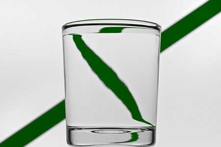
Note that, for a distant object, the cylindrical lens can produce a virtual image which is inverted across the width of the cylinder.
This inversion is shown in the photograph at left, in which the
virtual image of the green line in the background is inverted left to right.
The optics of a water glass. Photograph: Mike Gal
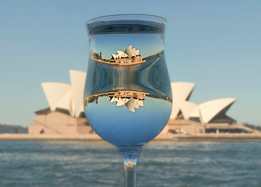
The optics of a wine glass. Photograph: Mike Gal
Now look at the photo at right (click on it for a larger version): there are three images of the opera house in this tulip-shaped wine glass. In all cases, the lens has rotational symmetry about a vertical axis so, as in the previous case, all three images are inverted left to right.
First, let's look at the top image. This is produced in a region of the glass which is convex left to right but concave top to bottom. So the image is inverted left to right, but not in the vertical direction. Second, we look at the image below, in the bulbous part of the glass. In this region, the glass is convex in both the vertical and horizontal directions, so the image is inverted left to right and also top to bottom. Finally, there is a tiny image in the top of the stem of the glass. Here the glass is convex left to right, but concave in the vertical direction, so the image is inverted left to right but is not inverted in the vertical direction.