Geometrical Optics Laboratory


Shadows

In general a shadow refers to a region where the light coming directly from a source is reduced or blocked by an object. For a point source of light, there will a distinct boundary between the shadow and the surrounding regions that are illuminated by light travelling directly from the source. However once the light source has finite dimensions, an intermediate region of partial shadow (the pen-umbra) occurs between the region of complete shadow (the umbra) and the surrounding illuminated region – see the figure below.


When investigating the details of shadows it is convenient to use a light source with adjustable dimensions and that provides uniform illumination. A computer screen can provide an ideal source. Set up the experiment shown in the photo below so that the white light from the computer screen falls upon a suitable round object (in this case a battery). Here I have used a cardboard box to raise the experiment to a suitable height. The locations of the source, object, umbra and pen-umbra can be marked on the sheet of paper. Drawing straight lines between the source and object as indicated in the figure above should explain the positions of the umbra and pen-umbra.


Several suitable figs are provided, but because they consist mainly of a black screen and are consequently not very interesting,  they have been placed at the end of this document.

Shadows on a celestial sale

The earth is illuminated by the sun and thus will cast a shadow. This is most obvious during a lunar eclipse, when the earth is located between the moon and the sun, and the shadow of the earth can be seen moving across the moon.

Simiarly the moon can also cast a shadow when it passes between the sun and the earth to produce a solar eclipse.

The earth can also cast a shadow on the evening sky known as the 'twilight wedge'. In favourable conditions a dark band will appear on the horizon oppposite to where the sun has just set. This dark region will grow vertically as the sun progressively travels further below the horizon. Eventually the edge of this darker region loses definition as the all of the sky becomes dark.


Reflection

When a wave in one medium is incident upon a second medium, some of the energy will not pass into the second medium, but be reflected back into the original medium. The angle of reflection equals the angle of incidence. This can be easily demonstrated using a mirror and a suitable light source.

For the photo taken below I used a torch with a narrow beam that was passed through a slit cut in cardboard.


A laser pointer can also be used, but heed the warning below.

WARNING: Never look directly at a laser pointer, or shine it at someone else. Also be careful about 'specular' reflections; i.e. those from mirror–like surfaces.

Corner Reflector

These are constructed from three mutually perpendicular flat mirrors. They have the property of reflecting incident light back in exactly the same direction, although the reflected ray will be displaced. To see why this occurs, imagine that the 3 planes defined by the mirrors are defined by x, y, z.

The example shown below was made from 3 small mirrors mounted at right angles.

A good way to test the reflector is to use a laser pointer. Because one should never look at the reflected beam of a laser, perhaps the simplest way to determine the direction of the reflected beam to attach a collar of white cardboard to the laser pointer - see the photographs below. It should be possible to rotateypur corner reflector and yetstiil ahve teh light reflected back towards the laser pointer.


Kaleidoscopes

The kaleidoscope involves multiple reflections from multiple mirrors. The idea occurred to Sir David Brewster whilst he was investigating polarization by reflection.He later patented the idea, but although the instrument was a huge success, he unfortunately made little money. The version shown below was constructed from 3 identical strips of plastic mirror (approx. 150 mm x 40 mm) arranged in an equilateral triangle (reflective surfaces on the inside) and bound with adhesive tape.


The photographs below were taken by holding the kaleidoscope to the end of a point-and-shoot camera, and photographing some of the coloured paper used for the experiments on colour mixing (sections of the Newton colour wheel can be seen).

Kaleidoscopes can be made with different numbers of mirrors arranged in different geometries. The three photographs below were made with the mirrors arranged in an equilateral triangle as shown above.


The photographs below were made with 3 mirrors arranged in an isosceles triangle or 4 mirrors arranged as a rhombus ( a diamond shape).


>

Refraction

When a wave is incident on a boundary between two different transparent materials, some of the light can be reflected and some refracted. The angle of incidence θ1 and angle of refraction θ2 are related by

n1sinθ1 = n2θ2

where n1 and n2 refer respectively to the refractive indices in the incident and transmitted media respectively.

One of the simplest methods to measure the refractive index is to use a rectangular slab of the material. You can use a laser pointer or a torch with a slit as the light siource. Most experimental kits for optics include a a rectangular glass slab. If you don’t have access to an optics kit I have found there are there are several household alternatives that include the following:.

• Glasses or vases with a square cross-section that have a heavy solid rectangular bas. Here is one that I purchased for a few dollars from a popular international furniture store.


There was a small circular depression in the base of this vase, so I needed to be careful that the light path didn't pass through this region.

• the small, solid plastic frames that used for small photographs.

• rectangular containers made from clear plastic with vertical sides. They can be filled with water, concentrated salt or sugar solutions, or other liquids. However analysis can be slightly complicated by the additional refraction of the pastic walls.

Measuring the angles θ1 and θ2 then yields the ratio n2/ n1.


Apparent depth

Another method of measuring refractive index of a liquid involves measuring the apparent depth of an object when viwed through that medium. This will require an optical device that can have its focal length fixed.

For a solid object of thickness d, first focus the device (I used a camera) so that a suitable object (I used a coin) is in focus. place the transparent object between the camera and the coin. Without changing the camera focus, move the camera a distance y away from the object so that the object is once again in focus.

The refractive index n of the material can then be calculated using

n = real depth / apparent depth = d/(d-y)

For liquids, the object can be placed at the bottom of a container and the camrar focussed. The container can then be filledwith liquid to a known depth and the above procedure repeated.

For thin objects a microscope can be used.

Total internal reflection

This can occur when a wave travels from a region with higher refractive index to one with a lower refractive index. Optical kits usually include a glass or plastic hemi-cylinder to make measurements easier. The critical angle from a medium to air is given by

sinθc = 1/n

where n denotes the refractive index of the medium.

If the medium with higher refractive index is a liquid, then it is possible to use a fibre optic to introduce the light.


Mirrors and lenses

Curved mirrors

Most experimental kits for optics will contain cylindrical convex and concave mirrors.
Flexible plastic mirrors also exist, but can be hard to find.

Fortunately there are several different types of suitable reflective adhesive tape available.

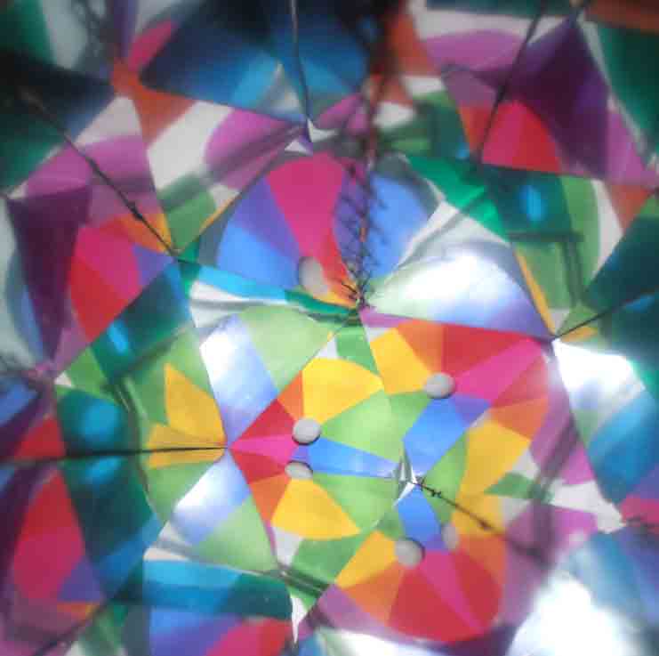
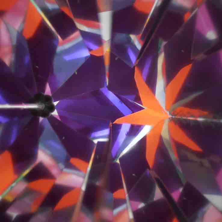
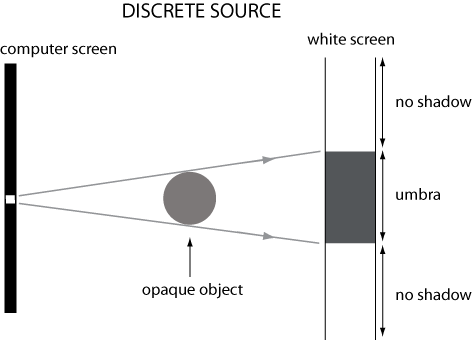
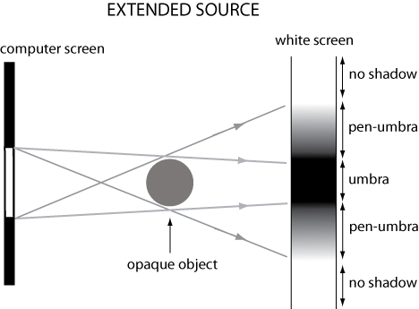
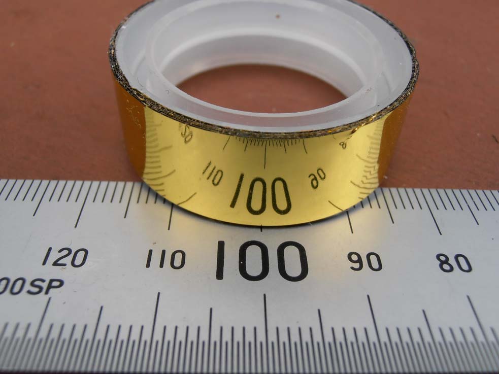
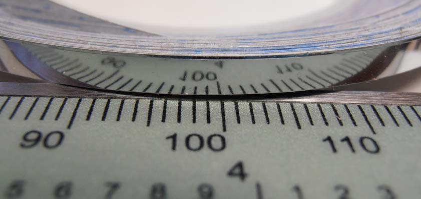
The two photographs below show two examples of this tape. The example on the right shows the highly reflective tape that some enthusiasts usefor 'pin-striping' cars. The 'chrome' version works quite well. The example on the left shows some reflective tape that is often used for decoration and for wrapping presents, particularly around the solstices. The best way to assess some tape is to look into it and see if you can see a clear reflection.

A concave cylindrical mirror can be made by sticking such tape around the outside of an appropriate glass or plastic jar.

A convex cylindrical mirror can be made by sticking tape to the inside of a plastic container that has been cut in half. If this turns out to be insufficiently rigid, a suitable slot can be cut into an intact container so that light can enter and exit.


.     


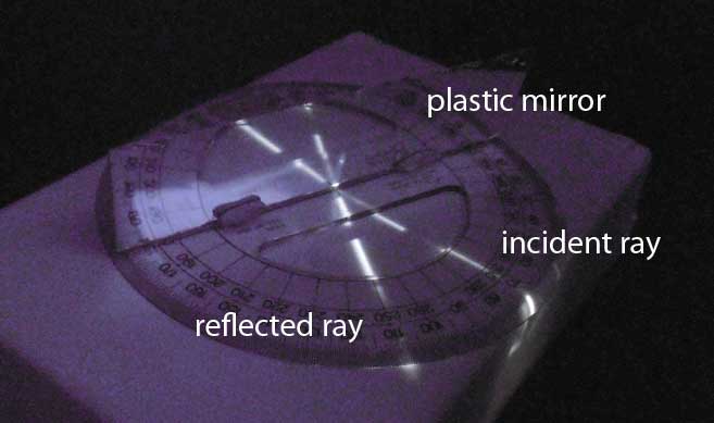
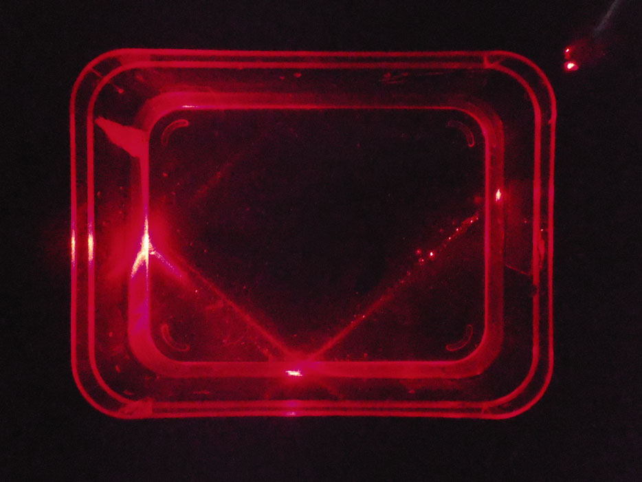
The photos below show two examples made with flexible mirrors.

Lenses

It’s relatively easy to find a convex lens. Examples include magnifying glasses or magnifying lamps, Can also be found in old discarded optical instruments (telescopes, microscopes., binoculars, etc). Also in some spectacles, but make sure that are not the sort where the focal length varies across the lens. Another possibly are drinking glasses and flower vases.

Many shops sell cheap plastic glasses usually in the range of +0.5 dioptres to +3.0 dioptres.

The focal length can be easily measured by focussing the light from a distant object (often a ceiling light is suitable) onto a sheet of paper. Or you can use the sun, but be very carefu lnot to set the paper alight.

The focussing power of lens should be simply additive - this can be checked by comparing the focal length of individual lensas with the focal length hen both are used.

Plano convex lenses

A convenient way to make these is to use a hemi-spherical or spherical bowl filled with water.

The expected focal length can be calculated from the measured diameter of the bowl and the refractive index of the liquid that fills it.

This can be compared with the measured focal length.

Thick lenses

These are lenses where the thickness of the lens becomes comparable with the focal length. We can consider three types

Thick lenses with 2 convex faces

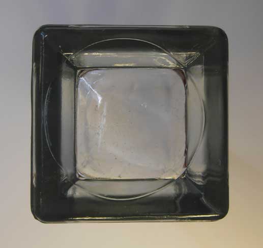
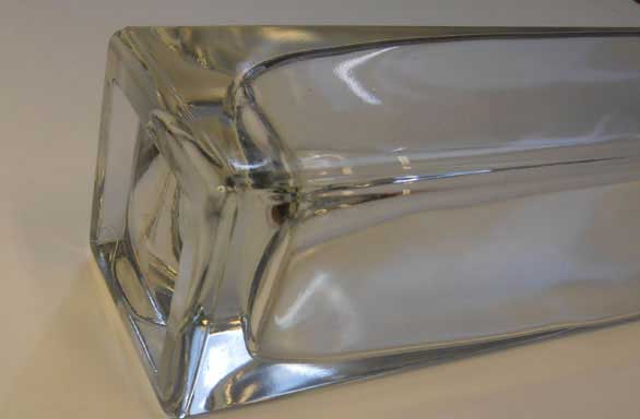
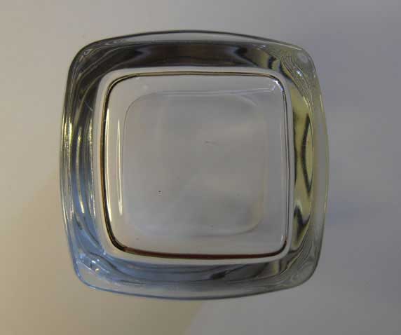
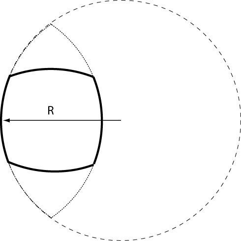
To demonstrate this I found 2 glasses with bases that had sides that were essentially sections of a circle - see figure.

See the photos below.


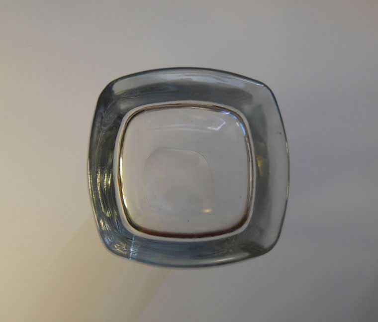
The radius of curvature of the two faces was determined by tracing the shape onto a sheet of paper, and comparing with a diagram on the computer screen.

The focal length was then calculated using the lens makers eqn.


The photograph below shows how the base of each drinking glass can be used as a magnifying glass.

t


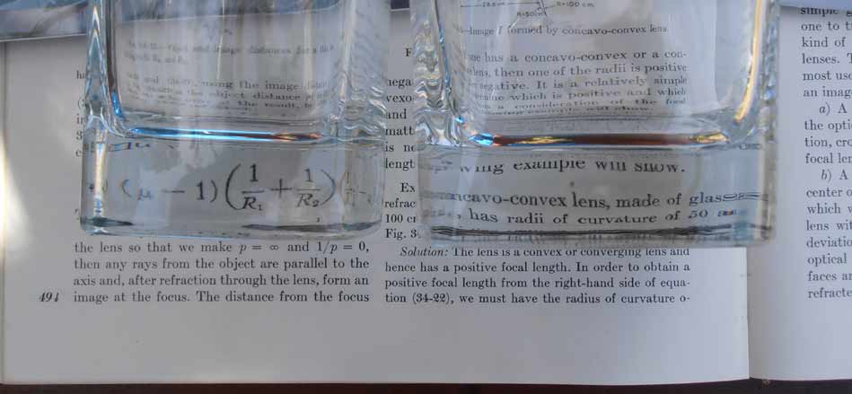
WARNING: The focal lengths of cylindrical and spherical lenses are similar to their diameters. If you put one in a sunny spot there is a good chance that the sun will be focussed onto something. I must admit to several scorch marks on my garden table from careless behaviour with such objects.

Cylindrical lenses

Possibilites include:

• a plastic rod

• Some drinking glasses have a heavy glass base that is cylindrical.

• many glasses have a cylindrical shape. These can be filled with water (or another liquid). If the glass is not perfectly cylindrical, be careful to use a section where the walls are vertical.

Spherical lenses

It is possible to find many solid spheres of glass or plastic. Otherwise a spherical container can be filled with water.

\Their refractive power is given by

Power of lens given by P = 1/f = (n-1)[1/R1 - 1/R2 + (n-1)d/nR1R2]

For a cylindrical or spherical lens R1 = R2 = R


Creative Commons License This work is licensed under a Creative Commons License.