Resonance Laboratory

Fig. 1. Equipment required for investigating the resonance frequency of a cantilever
These experiments are designed to investigate examples of mechanical resonances.
Fig. 2. Panel layout of the SINEGENX program

In each case we examine what happens when energy is input to the system via a small vibration at different frequencies.

This is achieved by running a sinusoidal signal generator program on a computer. The sinusoidal voltage from the computer's ‘headphone out’ socket is connected to the input of an audio amplifier with its output connected to a loudspeaker. See figure 1.

In case of accidents, the loudspeaker should be either old (its easy to salvage one from old equipment) or cheap.
The cone of the loudspeaker will then be driven in and out in an approximately sinusoidal fashion.

There are some constraints upon the frequency range we can use in these experiments. The low frequency limit is determined by the response of the electronics inside the computer and also the audio amplifier; these are usually designed to become inoperative at frequencies below 1 to 2 Hz to avoid accidental damage to loudspeakers, ears, etc.

A practical high frequency limit also occurs when the loudspeaker vibration frequency enters the range where our hearing becomes effective. The amplitude of vibration of the loudspeaker cone required to examine mechanical resonances can then produce uncomfortable or damaging sound levels

For these examples we use the SINEGENX signal generator program running on a Macintosh computer. (Full download instructions and accompanying manual - Mac version). 
(Links to similar software for Windows computers will also be added later).

Fig. 2 shows the panel layout of the SINEGENX program. In these experiments we will just use its ability to change frequency in precise, small increments.
For clarity we have enlarged the view of the signal generator in the accompanying movies so that only the frequency window is visible


Fig. 3. The cantilever, a plastic cable tie, is attached to a plastic cup with adhesive tape
Fig. 4. The loudspeaker is driven by the output of an audio amplifier.


Resonance of a cantilever

In this experiment we use a plastic cable tie as a cantilever beam.
First attach a plastic disposable cup the centre of a loudspeaker using Blu-Tack, or some other reversible adhesive.
The cable tie can then be attached to the cup using adhesive tape as shown in figures 2 and 3.

The variation of resonance frequency with length can be investigated by cutting sections off the end of the cable tie.

This movie clip shows a cable tie with 100 mm free length. This second clip shows the same cable tie, but shortened to 80 mm free length.

Resonance of a pendulum

For this experiment we make a simple pendulum using dental floss as the massless string and a small brass nut.
The loudspeaker with plastic cup attached is turned on its side as shown figure 5. We did this by allowing the speaker magnet to attach itself to a heavy steel object (in this case an adhesive tape dispenser).
The end of the dental floss is attached to the cup using adhesive tape. Remember the low frequency limit mentioned above: Choose the length of the string so the pendulum oscillates at a few hertz. Background information is here.

This clip shows how a simple pendulum will undergo resonance when driven around its resonance frequency.

The mass and string length can be easily varied.


Fig. 5. A simple pendulum is attached to a plastic cup.


We can also make a simple physical pendulum (i.e. one with distributed mass) by cutting the wire off one end of a resistor and bending the tip of the other into a little hook – see figure 6. A small hole can then be made in the rim of the plastic cup and the resistor attached so it swings freely – see figure 7.

This clip shows a such a physical pendulum.

Fig. 6. A physical pendulum made from a resistor.

Fig. 7. The physical pendulum is attached to the plastic cup.

Resonance of a mass on a spring

For this experiment we use a small mass (a brass nut) with a light piece of thin elastic as the spring. One end of the elastic is attached to the loudspeaker cone using adhesive tape and the loudspeaker placed upside down on a suitable support so the mass is free to move.

The mass can be easily varied by adding / subtracting small nuts. Background material on resonance and on Forced Oscillations and Resonance.


Resonances of a plate: Chladni patterns

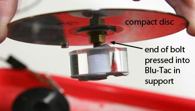
For this experiment we use a small circular plate; a CD that we have painted black so the Chladni patterns will show up better when filmed.

This plate is quite stiff, and would be difficult to attach directly to a loudspeaker. In the earlier experiments the sinusoidal motion of the cone of the loudspeaker occurred because a sinusoidal current flowed through the loudspeaker’s ‘voice coil’, which is immersed in a steady magnetic field and attached to the loudspeaker cone. This produced a sinusoidal force on the loudspeaker cone.

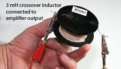
In this experiment we will drive the plate directly. The sinusoidal current is passed through a small inductor (a coil of wire with no magnetic core) and produces a sinusoidal magnetic field. This is then placed close to a small magnet attached to the plate, and so produces a sinusoidal force on the magnet.

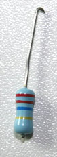
We used a 3 mH inductor from a loudspeaker crossover network – see figure 10.  The exact value doesn’t matter, any reasonably sized inductor should be OK.

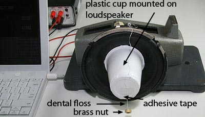
For this demonstration the plate as supported at its centre by means of a nut and bolt, the end of which was pushed in some reversible adhesive in a hole in some Perspex – see figure 9. However any rigid means of support that allows the plate to be horizontal would be OK.

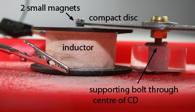
The experiment was then assembled in a plastic tray – this is important as otherwise sand gets everywhere. Two small magnets are placed on the edge of the plate. The inductor is placed so its centre is directly beneath the magnets and as close as possible to the plate without touching it – see figure 8. (If you get a buzzing sound during experiments, it probably means the magnet is too close and touching the vibrating plate.)

Now sprinkle some dry sand over the plate and increase the frequency (we used 1 Hz steps for this clip).

You can hear sound because the plate is vibrating and acting like a speaker cone.

The mode shown here is the (3,0) mode, although the Chladni pattern is slightly distorted by the mass of the two magnets.

Several other modes are possible for this configuration.

There are several possible extension sto this experiment.
You can move the magnets about the plate and investigate different driving points, either near to or far from the regions where the sand accumulates.
You can investigate how the way the plate is supported affects the patterns.
You can investigate how additional masses affect the shape of the Chladni pattern by adding extra magnets.
You can also try plates of different shapes and materials.


Fig. 8. The inductor is placed just under, but not touching, the magnets.

Fig. 9. The compact disc is rigidly supported at its centre.

Fig. 10. The sinusoidally varying magnetic field is produced by the sinusoidal current from the amplifier flowing through the inductor.


The non-linear pendulum

In section 1.4 we showed that a pendulum will experience a linear horizontal restoring force when its displacement from equilibrium is small and consequently sinθ ≈ θ. As the initial displacement increases, θ increases and so this approximation becomes increasingly invalid and the pendulum increasingly departs from SHM.

To investigate the consequence of this non-linearity, measure how the period of a pedulum varies with its initial displacement from equilibrium.

The clip below shows the difference in period produced by an extreme initial displacement.


Creative Commons License This work is licensed under a Creative Commons License.