Homopolar motors and generators are simpler than their multipolar cousins (see Electric motors and generators), but are very rarely used in practice. However, they illustrate the principles nicely, and a homopolar motor is both easy to make and easy to understand.
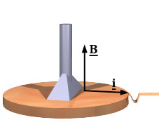
The permanent magnet in the animation (at left) produces a magnetic field B that is vertically upwards through the conducting disk. The cell provides current that flows through one brush to the central shaft, then outwards to the right towards the brush on the rim. The (conventional) current i is subjected to a force in the direction i X B, which is forwards, towards us. (Revise Vectors.) This force is transmitted to the disk, which rotates in the sense shown at left.
Because there is always a current path between the brushes (or at least there would be if they were ideal), the resultant torque is steady. Note that (in this version) there is only one current-carrying path, compared with many in a typical multipolar motor. On the other hand, the current could be large if the brushes had low resistance.
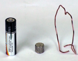
In a simple design for a very simple homopolar motor, the magnet itself (or its coating) touches the cell and is used as the contact for the brushes. In this design, the rotor is not a disk, but just a piece of wire with two current carrying paths (for balance). The piece of wire includes all three brushes. It uses a 1.5ĀV cell, one of whose terminals is the contact for one brush (the middle point on the wire), and a cylindrical rare earth magnet, whose circumference is the contact for the other two.
Safety warning: Because the battery is short-circuited by a piece of copper wire, this motor should only be run for very short times: it not only uses the battery very quickly, but also could heat it up, which is a potential safety hazard.
Homopolar Generators
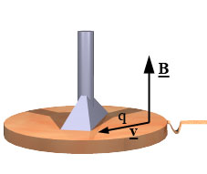
In the simple schematics below, we've made a homopolar generator by replacing the cell that drove the homopolar motor with a voltmeter. Whereas the homopolar motor converts electrical energy (supplied by the cell) into mechanical energy, the homopolar generator does the reverse: we provide mechanical energy to turn the disk and obtain an emf and (if a current path exists) an electric current.
The diagram above shows a mobile charge q travelling with the disk, and thus with velocity v at the point and time shown above. The charge is subject to the Lorentz force qv X B, which is towards the axle. This gives rise to an emf as indicated by the voltmeter (and a current if the circuit is complete).
Again, a homopolar generator is conceptually a little simpler than its multipole cousins but, because there is only one current path, the emf is small. (On the other hand, ideal brushes would in principle allow a large current.)
In our generator (above), one handle (left) turns the rotor and another (right) turns the magnet, which is the black block in the middle, just to the right of the two blue wires. The axis of rotation is horizontal, whereas that in the animation is vertical. The multimeter is reading mV DC.
Puzzles
The figure on the right shows a homopolar generator in which the rotor is not rotating (with respect to an inertial frame) and in which the magnet is not rotating. Our first question for you is this:
• If neither rotor nor magnet is rotating (with respect to an inertial frame*), is an emf produced?
Alright, too easy. And we've already seen what happens when the disc rotates and the magnet is stationary. Now to the remaining two possibilities, shown below.
• Ifrotor and magnet are both rotating (together, but with respect to an inertial frame*), is an emf produced? (Animation at left below.)
• Ifthe magnet alone rotating but the disk is not (both with respect to an inertial frame*), is an emf produced? (Animation at left below.)
*one in which Newton's laws hold and in which the distant stars and galaxies are not rotating around the earth.
Variations on homopolar generators
Think carefully about these questions before you answer and before you look at the film clips below. In science, the authoritative answer is always obtained by asking the universe – i.e. we do the experiment. So the film clips below show the interesting configurations: both rotor and magnet rotating, and magnet rotating but rotor not rotating.
This homopolar generator has one handle (left) that turns the rotor and another (right) that turns the magnet. The multimeter is reading mV DC.
In the clip below, a pad is inserted between the rotor and the magnet, with the consequence that both turn: after the initial transient, there is no relative motion between rotor and magnet.
So, will it produce an emf?
In this
clip, the pad is removed, but I turn the handle that rotates the magnet. The rotor remains stationary. So in this case there is relative motion between rotor and magnet. So, will it produce an emf?
If your mind is boggled, don't worry, you are in excellent company! Go back and have a look at the discussion of the operation of the homopolar generator above. Think about the Lorentz force. You might also find it helpful to think about what a magnet is like at the atomic level and what it means to rotate a magnet.
When I was a student at the Australian National University, there was a large homopolar generator (actually two homopolar generators in one device), used for experiments requiring megamperes of current.
A diesel engine would drive the rotation of two 40 tonne rotors up to an angular velocity of 900 revolutions per minute, eventually storing 500 MJ of energy in its rotation. (I can't remember the details of the engine, but if it delivered 50 kW, it would take three hours to spin the disk up to 500 MJ.) Then the 'brushes', which were made of liquid sodium or a (liquid) mixture of sodium and potassium, would be brought into contact and that mechanical energy would be rapidly turned into electrical energy. Yes, it was a dangerous device.
Remains of the rotor are still there, making an impressive sculpture at the Eastern end of the Research School of Physical Sciences and Engineering (photo at right). See The Big Machine for some of the details and history. What impressed me most was the lathe on which the components had been made. Most lathes are measured by the maximum diameter that can be held in the chuck, which is typically measured in centimetres. The lathe used for this had a 7 m chuck.