Reflections and the conditions for constructive and destructive interference
 |
|
Reflections and phase changes at the glass-air interfaces
|
This sketch shows the geometry close to the point* of contact between the convext lens (top) and glass flat (bottom). The other surfaces (the top surface of the lens and the bottom surface of the flat) are assumed to be so far away that reflections from them don't produce interference fringes: see Coherence length.
* Only in the macroscopic view is there a point of contact. Real materials are not infinitely rigid and so they deform at contact and may even weld together.
Consider first the arrows closest to the point of contact, where the separation t between interfaces is rather less than a quarter wavelength, λ/4. Now consider the reflection from the top surface and that from the bottom: the two parallel rays travelling upwards. The component of phase difference between these two that is due to their different pathlength, which is much less than π.
Now consider the phase difference due to reflections. (See Reflections and phases for an introduction.) At the upper surface, the ray reflects going from glass towards air – high n to low n – so the phase change is zero, as indicated on the sketch. At the lower surface, the ray reflects going from air towards glass – low n to high – so the phase change is π. So, with small phase change due to path length but a π phase change due to the two reflections, these two rays are about π radians or half of one cycle out of phase, which gives destructive interference. Consequence: in this region close to the point of contact, there is destructive interference in reflection.
Next consider the middle set of rays in the sketch. Here the thickness is t = λ/4, so the path difference is 2t = λ/2. This gives a phase difference of π. Add this to the π from the reflections and the phase difference is 2π – the two rays are out of phase by one complete cycle. So, provided the coherence length is sufficiently long, these rays give constructive interference in reflection.
Finally, the rays in the sketch at left are for an air film thickness of t = λ/2, so the path difference is 2t = λ. This gives a phase difference of 2π. Add this to the π from the reflections and the phase difference is 3π – the two rays are out of phase by one and a half complete cycles. This time we have destructive interference in reflection.
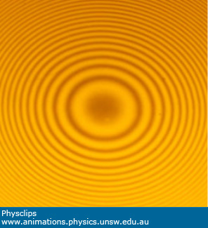
And so on: our thin film has a varying thickness, so we have different interference conditions at different thicknesses. This leads to the alternating rings of constructive interference (bright rings) and destructive interference (dark), as shown in the photograph. We can use these rings to determine the radius of curvature of the lens surface, as shown below. But first, let's stop to think about:
Newton's rings in transmission
In the sketch and discussion above, we don't show the further transmission and reflections. However, only part of the enery in the rays in the air is reflected: the rest is transmitted. The rays transmitted here have respectively no reflections and two reflections going from air towards glass, so 0 and 2π radians phase change. So the transmitted rays near the point of contact have constructive interference in transmission. So, in a Newton's rings pattern in transmission are like negative images of those seen in reflection: a bright patch at the centre followed by a dark ring, then a bright, etc. You can also arrive at this conclusion from conservation of energy: where the energy is not reflected, it must be transmitted, so bright rings in reflection correspond to dark rings in transmission, and vice versa.
|
The radius of the rings gives the radius of curvature of the lens
|
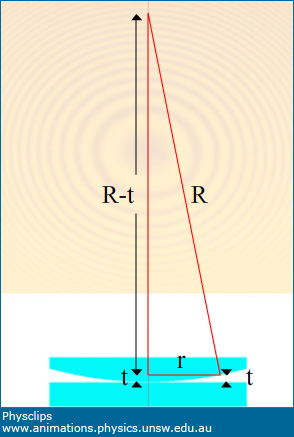
The global geometry of Newton's rings |
Let's consider a dark ring with radius r at a point where the separation is t. The right angled triangle shown in red has a height R–t so Pythagoras' theorem gives us
Here, t is several wavelenths or so, while the ring radius r is usually some millimetres, so we can neglect the
t2
term. Further, for a dark ring, we have seen above that t = mλ/2, where m is a positive integer. Substituting gives
So a plot of r2 vs m, the number of the dark ring, gives a straight line whose slope is Rmλ.
|