| |
|
|
|
||||||||
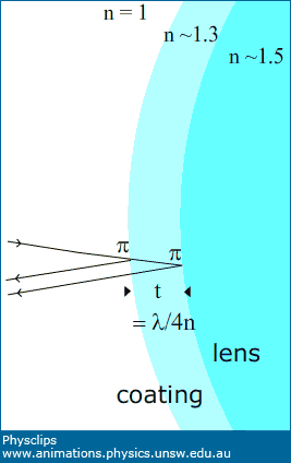
The structure of a non-reflective coating
The refractive index of the non-reflective coating lies between those of the lens and the air: nair < ncoating < nglass, as suggested in the sketch. Part of the energy in the ray arriving from air towards the coating (small n to large n) is reflected with a phase change of π. (See Reflections and phases for an introduction.) The rest is transmitted and arrives at the interface with the glass. Again there is partial reflection, with the reflected ray (again, small n to large n) having also a phase change of π. So, comparing the two reflected rays, there is no component of the phase difference due to reflection: these effects cancel out. Let's consider a wavelength λ in air and so a wavelength λglass in the glass. Now suppose that thickness of the layer is t = λglass/4 = λ/4n. So the second reflected ray has travelled λglass/2 further, so that the phase difference, entirely due to the path difference, is π. So, for this wavelength, we have destructive interference: very little power is reflected from the coating, and most is transmitted into the lens: more light is available for the optical instrument, whatever it is, and less is wasted in reflection. For optical instruments, one would usually choose λ to be in the middle of the visible spectrum (green light at around 550 nm). So, on the axis and with normal incidence, there is maximum destructive interference for green, but still considerable destructive interference for the rest of the visible spectrum. We've discussed only the on-axis rays (and neglected the angle of incidence in the schematic above). When the angle of refraction in the coating is θ, the pathlength difference is λ/(2n cos θ): longer by a factor of 1/cos θ. So the destructive interference is more complete for longer wavelengths – towards the red end of the spectrum – and the destructive interference is less complete for blue and violet. This explains why the lens in the photo above appears to havea blue-violet tinge – which provides a simple way of recognising such coatings. |
||||||||
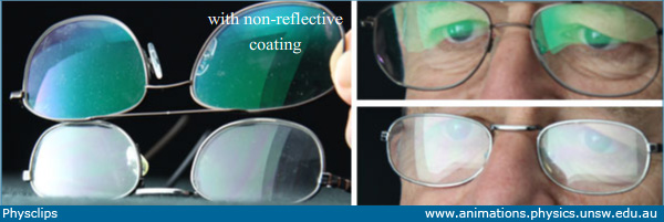
Non-reflective coating on spectacles
These photograhs show the effects of non-reflective coatings on spectacles. In the photo at left, we see less light reflected from the spectacles with the coating (and, as explained above, the destructive interference is more effective at the red end of the spectrum, because the photo is taken off axis). The non-reflective coating allows more light into the spectacles – the eye receives more light. Another effect is that another observer can see the wearer's eyes better, because less reflected light from the spectacles is added to that reflected from the wearer's eyes. |
||||||||
Destructive interference in reflection – wave caricature
This cartoon uses the wave caricature of light to show how the non-reflective coating produces destructive interference. The wave is partially reflected at the first interface (low to high n) with phase change π. At the second interface (again low to high n), it is also reflected with phase change π. The thickness is set so that t = λglass/4 = λ/4n. So the second reflected ray has travelled λglass/2 further, so that the phase difference, entirely due to the path difference, is π. Note that, in this cartoon, we have not shown the rays transmitted at the coating-glass interface, nor those that are reflected going from coating towards air. If these were included, they would produce constructive interference in transmission. We leave the details of that argument to you. You can also make this conclusion from energy considerations: if little energy is reflected due to destructive interference, then most of the energy must be transmitted. | ||||||||
Destructive interference in reflection – photon caricature
But what if we think of photons? This cartoon shows both the wave caricature and the particle caricature of light. If photons were particles, we could represent them by the red dots in this animation. This leaves us with a puzzle: suppose a photon strikes the first interface and is reflected (as shown). Once it is reflected, how can it be 'unreflected' by subsequent photons that reflect from a surface further away? We discuss this question further on this link. Further information
| |||
|
||||||||