Linear and non-linear superposition
Superposition of oscillations in a nonlinear medium or system introduces complications. The multimedia chapter Interference and consonance introduces linear superpostion, interference and consonance. Here we revise some those ideas and extend them to include superposition in a nonlinear system.
This animation illustrates just a few of the complicated superpositions that occur when multiple sources produce sound.
The pressures of sound waves are usually very much smaller than atmospheric pressure, which means that air is a highly linear medium for sound, as we saw when deriving the wave equation for sound. Our ears, however, do not respond linearly to sound, so it is interesting to compare linear and non-linear superposition. To explain the differences, we'll use some simpler systems made from electronic components.
A simple linear system
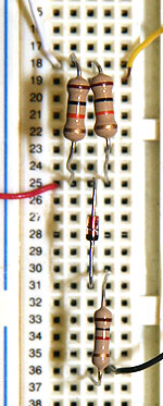
 This photograph shows a linear system: voltages V 1 (on the white wire) and V 2 (on the yellow wire) are the two inputs, each connected to a resistor r = 1 kΩ and V (the red wire) is the output across a resistor R = 1 kΩ. (All voltages are with respect to the ground: the black wire.) This circuit is linear because resistors are linear: the voltage across a resistor is proportional to the current through it. So we can write
where (applying Kirchoff's laws we see that) α = β = 1/(1 + r/R) and, with these values of r and R, that is 1/2.
The oscilloscope screens show this for a simple example in which V 1 and V 2 are sinusoids with frequencies (1.6 and 2.0 kHz respectively). The fourth screen is that of a spectrum analyser that displays V. (The apparatus is the same as that used for Lissajous figures.) The spectrum analyser shows just two frequencies present, those of V 1 and V 2, which we'll call f and g respectively henceforth.
At top left we see V1 and V2 on the two traces. Top right shows V1 + V2, using the same time scale as at left. At bottom left, we show successively the outputs of three different circuits, one linear and two non-linear. (We repeat this figure below with more explanation.) At bottom right is the spectrum of the output, which is also what we hear on the sound file.
|
A simple nonlinear system
|
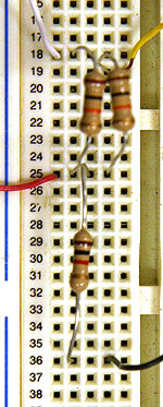
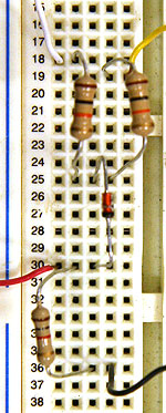 Now let's add a nonlinear element: a junction diode. To a good approximation, the current in one direction (against the arrow in the circuit symbol) is zero for a wide range of voltage. In the other direction, the voltage increases approximately exponentially with voltage, so we can write Now let's add a nonlinear element: a junction diode. To a good approximation, the current in one direction (against the arrow in the circuit symbol) is zero for a wide range of voltage. In the other direction, the voltage increases approximately exponentially with voltage, so we can write
i ~ i0 ln (Vdiode/24 mV − 1) if Vdiode > 24 mV
i ~ 0 if Vdiode < 24 mV
This is a very nonlinear relation, especially around the origin. Note that the output voltage V (the red wire) measures across resistor R, so it is proportional to the current in the diode.
An expression for V(V1,V2) is rather messy in both nonlinear cases shown below. However, for the circuit shown at right, the output voltage is proportional to the current in the diode, which is always in the same direction. So this circuit clips the output: it cuts off any negative values. Clipping is a common nonlinear operation, often used in sound to produce higher harmonics (it's called fuzz on guitar effects pedals). Here the clipping is rather severe, so we see the strong heterodyne components with frequencies f+g, f–g, 2f+g, f+2g, etc.
Why 24 mV in the equations above? At room temperature, kT/e = 24 mV, where k is Boltzmann's constant, T the absolute temperature and e the electron charge. The Boltzmann distribution specifies the proportion of electrons (or atoms, molecules etc) having a given energy E: the proportion varies as E/kT = eV/kT. More on this later when we do thermal physics. |
Listen for
the difference components – the low note with frequency f−g – in the last part of the sound file. Then, to hear more examples, see Tartini tones.
|